
A casting can be vulnerable to failure at a local hot spot even when the component appears adequately designed overall. Stress concentration occurs when geometry or a material flaw raises stress in a limited area. The stress concentration factor (Kt) is the ratio of peak stress to reference stress. Casting design for stress reduction focuses on high-stress regions, such as sharp corners, holes and notches, and uses geometry that distributes loads more gradually.
Designers know that a casting’s shape affects how it carries loads. Abrupt changes in section thickness, sharp edges and discontinuities can intensify local stress, while smoother transitions can help reduce concentration and the risk of cracking or distortion. The challenge is to improve the geometry without compromising the stiffness or functional features the component requires.
This article explains how stress concentration forms, how casting geometry affects stress and distortion, and where fillets, tapers and other design changes may help. It also describes how analysis can guide design decisions and what engineers should consider when developing iron castings for demanding service conditions.
Key Takeaways
- Look for sharp corners, holes, notches and abrupt section changes, where local stresses can rise and threaten component performance.
- Use gradual geometry transitions, such as fillets and tapers, to help distribute loads while preserving the stiffness required by the design.
- Consider how casting flaws and surface irregularities can create vulnerable regions, particularly when a component experiences cyclic loading.
- Use stress analysis to assess design changes and predict how geometry and cooling may affect residual stress and distortion.
- Define the stress concentration factor as peak stress divided by reference stress to help compare vulnerable features in a component.
Abrupt geometry changes and component discontinuities
In a cast component, a sharp change in section can redirect load into a small region. The stress concentration factor depends on the part’s geometry: greater discontinuities and irregularities produce higher factors. For example, a thick boss joining a thin wall creates a more abrupt load path than a gradual transition. Under service loading, the junction can experience higher local stress than the surrounding material.
Corners, holes, cracks and notches are common stress concentration sites in machine parts. A hole through a loaded flange interrupts the material carrying tension. A keyway in a rotating shaft removes material and changes the local geometry. Oil grooves, screw threads and splines also create discontinuities. Position matters: a groove beside a loaded shoulder can combine with the shoulder’s geometry to raise local stress.
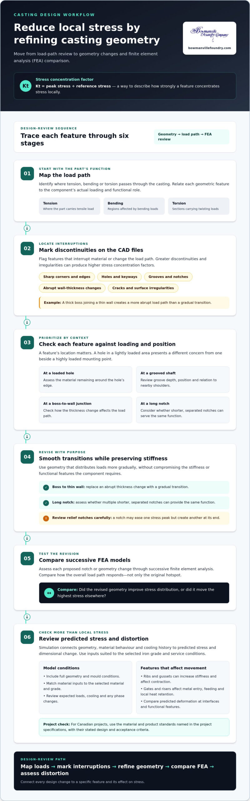
During design review, map each feature against the component’s load path. Mark holes, keyways, grooves, notches and abrupt wall changes on the CAD files. Then identify which features lie where tension, bending or torsion passes through the casting. A hole in a lightly loaded area presents a different concern from one beside a highly loaded mounting point. This feature-by-feature review makes casting design for stress reduction specific to the part’s function.
- At a boss-to-wall junction, replace an abrupt thickness change with a gradual transition.
- At a loaded hole, assess the remaining material around its edge.
- At a long notch, consider whether shorter, separated notches can serve the same function.
- At a grooved shaft, review the groove’s depth, position and relation to nearby shoulders.
Relief notches can help reduce stress concentration, but their shape and placement need analysis. Assess each proposed notch through successive finite element analysis (FEA). A notch that eases one local stress peak can create another at its end. Comparing successive models helps show whether revised geometry improves the overall load path or simply moves the highest stress elsewhere.
Large size changes between loaded features can also compromise stiffness. For example, an oversized transition between two mounting regions may change how the part deflects under load. Preserve stiffness by keeping changes proportionate to the component’s structural role. Where a long notch cannot be avoided, multiple shorter notches may reduce concentration compared with one continuous notch. The resulting geometry still needs FEA review.
Changing the original part design is described as the most economical approach in the manufacturing chain. Apply this principle early: review discontinuities before tooling and production decisions are fixed. A practical sequence is to map loads, mark geometric interruptions, revise transitions, then compare successive FEA results. This connects each design change to a specific feature and its effect on stress.
Casting stress and distortion prediction
Simulation connects part geometry, material behaviour and cooling history to predicted stress and dimensional change. For Canadian projects, use the material and product standards named in the project specifications, along with their stated design and acceptance criteria.
Material-Specific Design Recommendations
Design recommendations vary with the selected casting material and grade. For aluminium, account for the specified alloy’s properties and solidification behaviour; for iron, use data suited to the iron grade and its service conditions. A simulation should use matching material inputs rather than assumptions transferred between material groups. Review expected loads, cooling and any phase changes when assessing the finished component.
Detailed stress analysis may benefit from comprehensive mould data. Stress simulation can take more CPU time than filling and solidification models because it has more degrees of freedom. Include the full geometry and mould conditions, then compare predicted deformation with the component’s functional requirements. This connects model results with actual interfaces and assembly needs.
Rib and Gusset Effects
Ribs and gussets can increase stiffness, but their junctions also affect contraction during cooling. A thick rib joining a thinner wall may cool differently, causing uneven shrinkage or distortion. Review rib thickness, orientation and attachment geometry together. For a supported housing, compare predicted deformation around each rib and mounting surface, then adjust the shape without compromising the stiffness needed under service loads.
Assess each revision in the full model. A gusset that limits movement near one support can redirect deformation elsewhere. Compare the location and direction of predicted movement across the component, not only at the reinforced junction. This clarifies how the change may affect assembly faces and other functional features.
Gating and Riser Design
Gates and risers influence metal entry, feeding and local heat retention during solidification. Their arrangement can affect temperature gradients and the sequence of contraction. Include the gating and riser layout when evaluating residual stress and distortion. For a casting with a heavy hub and thinner arms, assess whether the predicted cooling sequence causes uneven movement between those regions.
Use simulation results to compare alternative arrangements against the part’s required geometry. Review heavy sections, restrained areas and interfaces where movement could affect fit. Assess gating or riser changes using the complete mould model, since isolated changes may alter feeding and cooling elsewhere.
Residual Stress Measurement and Reduction
After manufacture, assess residual stress using suitable measurement methods alongside dimensional inspection and simulation. Compare measured dimensions with predicted allowances, and examine where differences occur. A mismatch near a machined face, for example, can guide model refinement and highlight a feature requiring closer review. Interpret measurement results in relation to the component’s geometry, material and service requirements.
Controlled heat treatment can reduce residual stress in iron castings. The process involves heating, holding for a defined period and controlled cooling. Treatment choices depend on the iron, geometry and required dimensional stability. Assess the treatment alongside measurements taken before and after processing to evaluate its effect on the part.
Effects of stress concentration on casting durability and failure
Internal cracks, cavities, blow holes, inclusions and gas pores can increase stress concentration in a casting. Each defect interrupts the material and creates a local region where stress may rise. For example, a pore near a loaded bore can compound the effect of the bore’s geometry. Under repeated service loads, a crack can become a starting point for further damage.
Stress concentration makes localized regions more vulnerable to higher stress than the surrounding material. Under static loading, a concentrated region can initiate cracking, particularly in brittle material. A crack can affect how stress is distributed through the part. The component may then fail from a local defect even when its overall shape appears adequate.
Cyclic loading creates a different durability concern. Repeated loading and unloading can contribute to failure in ductile materials when cracks, flaws, sharp discontinuities or rough surfaces are present. Consider a bracket that experiences repeated force at a mounting hole. A nearby pore or rough surface can compound the hole’s geometric interruption, increasing the risk of crack initiation.
Assess defects and geometry together, rather than as separate concerns. A smooth surface does not remove an internal cavity, and a sound casting can still have a severe stress raiser at a sharp feature. For a loaded flange, review the hole edge, adjacent wall thickness and casting integrity as one region. This combined assessment connects inspection findings with the component’s actual load path.
Use a practical review sequence for a suspect component:
- Locate cracks, cavities, blow holes, inclusions and gas pores.
- Map those findings against holes, notches and other loaded features.
- Identify whether the part experiences static or cyclic loading.
- Assess surface roughness near regions exposed to repeated stress.
- Relate each defect’s position to the component’s function and failure mode.
A pore far from a loaded feature presents a different condition from a pore beside a keyway under cyclic torque. Likewise, a crack near a highly loaded mounting point merits attention alongside the surrounding geometry. These examples show why defect location and loading context matter: a defect’s mere presence does not describe the full risk.
When reviewing failure evidence, connect the fracture origin to the casting’s geometry and operating load. A crack beginning at an inclusion suggests a material flaw; one beginning at a sharp notch points to a geometric discontinuity. Surface roughness or gas porosity near either origin may also contribute. This evidence helps engineers decide whether design changes, casting inspection or both should guide the next revision.
Stress concentration does not make failure inevitable, but it identifies where durability needs closer assessment. For instance, a ductile component under repeated loading needs review for cracks, flaws and surface condition around loaded features. A brittle component under static loading needs attention to concentrated sections where cracks may begin. Matching material behaviour, defect location and service loading gives engineers a clearer basis for evaluating casting failure risk.
Avoiding sharp corners and edges
A sharp internal corner changes the direction of force over a short distance. At a bracket’s inside corner, load travelling through one wall must turn into another. A small radius makes that change abrupt, concentrating stress near the junction. A fillet replaces the corner with a curved transition, helping distribute load through a broader region.
Fillet radii are commonly used to avoid sharp corners and edges in component geometry. They are especially relevant where a boss, rib or flange transfers load into a wall. For example, a mounting boss joined to a plate with a square shoulder creates an abrupt transition. A rounded junction gives the load path a more gradual change in direction.
Along load-transferring paths, make fillet radii as large as practical. The required radius still needs to suit the component’s function and surrounding features. A large radius could interfere with a mating part, fastener seat or machined surface. For a bolted housing, check clearance around the bolt head before extending the fillet.
Use stress concentration charts when selecting a fillet radius. A chart helps relate the radius to adjoining section dimensions and the resulting concentration factor. Compare candidate radii for the specific geometry rather than selecting one by appearance alone. For a stepped shaft, for example, evaluate the shoulder radius against the shaft diameter and the adjoining larger section.
Tapers offer another way to replace abrupt geometry changes. A tapered transition between thick and thin sections spreads the change over distance instead of concentrating it at one shoulder. On a cast arm joining a thicker hub, a taper can soften the transition while maintaining the required connection. Review the resulting form against the load direction and available space.
Use a repeatable review sequence when revising a corner:
- Identify the load-transfer path and the sharp junction.
- Check nearby holes, bosses, machined faces and mating components.
- Compare a fillet or taper against the original geometry.
- Consult stress concentration charts to assess possible radii.
- Review the revised geometry with finite element analysis.
Relief notches need particular care at their ends. A notch can reduce concentration along a long interruption, but its termination may create a new local peak. Successive finite element analysis can compare notch shapes and show whether the peak moves or falls. For a loaded flange with a long slot, compare the original end shape with a rounded termination and alternative relief geometry.
Apply these changes without removing material needed for stiffness or function. A fillet around a loaded flange should not obstruct a mating surface; a taper around a boss should preserve its connection to the wall. In practical casting design for stress reduction, balance a generous transition with clearances, load transfer and section requirements, then assess the revised geometry as a complete part.
Definition of stress concentration
The stress concentration factor, written as Kt, compares peak stress with reference stress. It is expressed as Kt = maximum or peak stress ÷ average or reference stress. Because both values describe stress, the ratio has no stress unit. For example, an engineer can use Kt to compare local peak stress with the nominal stress used in a component calculation.
Consider a flat casting under tension, with a hole through its centre. The material around the hole carries load through a reduced, interrupted path. Peak stress near the hole can exceed reference stress across the wider section. Kt describes that increase for the geometry and loading being assessed. It does not, by itself, describe the casting’s complete service performance.
Define reference stress consistently to make a useful comparison. In a design review, record the applied loading, the section used to calculate reference stress and the location of peak stress. Then compare those conditions across design iterations. If a hole moves closer to a loaded edge, reassess the local geometry rather than assume the earlier Kt still applies.
Geometry helps explain why Kt changes. A smooth, gradual transition generally interrupts a load path less abruptly than a sharp internal corner. A notch end, keyway or threaded feature can create a local peak because each changes the component’s shape. When evaluating a cast bracket, for example, identify both the boss junction and nearby mounting holes before comparing stress results.
Use Kt as part of a structured review, not as a stand-alone pass-or-fail value. The factor relates peak stress to reference stress, while material condition, casting flaws, loading type and component function also inform durability assessment. A pore beside a notch presents a different review case from the same pore in a lightly loaded region. Location and load path matter.
A practical comparison can follow these steps:
- Define the component’s reference stress and loading condition.
- Mark the feature where peak stress is expected.
- Calculate or obtain peak stress for that geometry.
- Divide peak stress by reference stress to determine Kt.
- Compare revised geometries under consistent model assumptions.
For example, compare a sharp shoulder with a radiused shoulder using the same material, load and boundary conditions. The resulting Kt values can show how geometry changes local stress concentration. Keep model assumptions consistent; otherwise, a changed result may reflect altered conditions rather than the revised shape. Connect the comparison to the casting’s intended loads and functional constraints.
For an iron casting design review, discuss your casting design with the foundry team and explain the component’s geometry, loading and performance requirements.
Bowmanville Foundry: Malleable Iron Castings
Bowmanville Foundry produces Malleable Iron Castings for components that require tensile strength and ductility. Consider material selection and part geometry together, particularly where service loads affect critical features.
Bowmanville Foundry was the first foundry in Canada to achieve ISO certification in 1996. It also operates a modern, clean foundry, providing relevant quality and facility context for casting buyers.
Alongside Malleable Iron Castings, Bowmanville Foundry produces Ductile Iron Castings and provides Post-Processing Services. These offerings support projects requiring iron components or finishing after casting.
Contact Bowmanville Foundry or visit bowmanvillefoundry.com to discuss your casting requirements.
Take the next step with your casting design
Carry the stress review into the part definition before finalizing geometry and production requirements. A useful design package connects the CAD model with material requirements, service loads, critical interfaces and areas where machining or assembly limits the shape. This gives the design discussion a clear engineering basis.
For casting design for stress reduction, consider how the selected iron grade and finishing requirements relate to the component’s function. Bowmanville Foundry produces Malleable Iron Castings and Ductile Iron Castings, and provides Post-Processing Services. Share your part requirements with Bowmanville Foundry to discuss how these services fit your project.
Contact Bowmanville Foundry to discuss your casting requirements or arrange a visit. A focused conversation can help move the design from analysis toward a practical next step.
Frequently Asked Questions
What is Stress Concentration?
Stress concentration is a localized increase in stress around a feature or flaw compared with the wider component’s nominal condition. For example, a loaded mounting ear can experience higher local stress beside its bolt opening than across the adjoining web. Engineers assess that location alongside applied loads and material behaviour, then determine whether the feature needs a geometry revision or closer inspection.
Why Use Casting Stress Simulation?
Casting stress simulation helps engineers compare how design and process changes may affect a part before production decisions are fixed. For instance, a pump housing model can compare alternative support layouts and identify areas where predicted deformation may affect an assembly interface. Simulation is most useful when the model reflects the component’s geometry, mould and material, and when results are interpreted against functional requirements.
What casting design principles reduce stress concentrations?
Keep load paths direct, avoid unnecessary interruptions and assess each feature against its function. For a cast mounting bracket, review the bolt pattern, support points and mating surfaces together rather than changing one feature in isolation. Preserve stiffness where loads enter or leave the part, and compare revisions under consistent loading assumptions. This helps engineers distinguish useful geometry changes from those that simply shift stress elsewhere.
How do fillets and radii affect stress in cast parts?
Fillets and radii soften transitions where two surfaces meet, helping reduce abrupt changes in the load path. For example, adding a radius where a bracket arm meets its base can ease stress at that junction. The shape must still leave room for fasteners, mating components and required machining. Review the complete interface, since a radius that improves one corner may conflict with another part’s fit.
How should wall thickness and section transitions be designed to reduce casting stress?
Keep wall-thickness changes gradual and avoid placing major section changes directly beside loaded features. In a cast housing, a sudden thick-to-thin transition near a mounting point can create uneven stiffness and complicate load transfer. Check the transition against adjacent ribs, openings and machined faces. A revised wall profile should maintain functional stiffness while giving the geometry a more continuous form.
How do design recommendations differ for aluminum, steel, and iron castings?
For aluminum, account for the specified alloy’s properties and solidification behavior; for iron, use data suited to its grade and service conditions. Simulation inputs should match the selected material rather than transfer assumptions between material groups.
