
A wall that appears vertical can be the difference between a clean release and a casting that drags against the die. A die-casting draft angle is the taper on a wall that lets the part release as the die opens; a commonly recommended range is 1 to 3 degrees, with the suitable angle depending on the surface, depth, alloy and tooling. The importance of a casting draft angle lies in making ejection easier while protecting the part and die from avoidable damage.
Draft may seem like a small design detail, but it affects how a casting releases from the tooling and can influence surface condition and dimensional accuracy. The importance of casting draft angle goes beyond a general rule of thumb: the right angle depends on the part and how it is made.
This article explains where draft is needed, how the die’s draw direction determines which faces require it, and why internal walls and cores may need different treatment from external walls. It also covers the effects of insufficient draft, including drag marks, ejection stress and faster die wear, so you can weigh the design trade-offs before tooling decisions are made.
Key Takeaways
- Draft is the taper that helps a casting release from its tooling; the appropriate angle depends on the process, surface geometry and other design requirements.
- Use the die’s direction of draw to identify which faces need draft, paying particular attention to walls parallel to the draw.
- For sand-casting patterns, draft allowance changes with wall height, so avoid applying one angle to every surface.
- Balance easier release against dimensional tolerances and surface appearance when reviewing draft, texture, ribs and internal features.
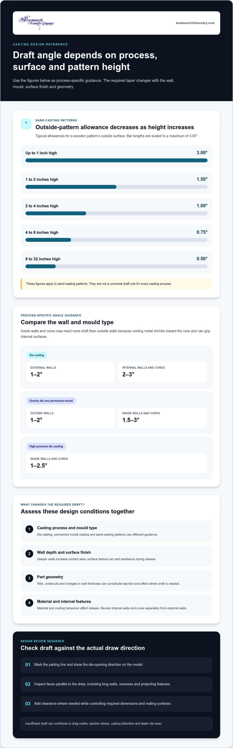
- Insufficient draft can contribute to drag marks, ejection stress, casting distortion and faster die wear.
What is Draft Angle in Die Casting?
A draft angle is the taper on a mould wall that helps a casting release during ejection. The appropriate angle depends on the casting process, material, wall depth, surface finish and tooling geometry.
Draft on Inside and Outside Walls
Outside-wall draft tapers the casting’s external faces, while inside-wall draft opens internal faces and cores in the direction of release. The distinction matters because cooling metal shrinks toward the core, which can grip internal surfaces more firmly. As a result, inside walls often need more draft than outside walls. For die casting, typical guidance is 1 to 2 degrees on external walls and 2 to 3 degrees on internal walls and cores.
Wall thickness also affects how designers balance release with the required part dimensions. General die-casting recommendations include 1.0 to 2.5 mm for zinc walls and 2.0 to 3.0 mm for magnesium walls. These are material-specific design figures, not draft angles. A thicker or thinner section can change the part geometry and its relationship to the tooling, so draft and wall thickness need to be considered together.
Factors Affecting Draft Angle
Draft selection depends on the material, mould type, casting depth, surface finish and part geometry. These factors affect how a surface contacts the mould and how readily the casting releases. A deeper wall increases the contact area, while texture can add resistance. Ribs, undercuts and changes in wall thickness can also complicate ejection and affect where draft is needed. These fundamental tooling principles also extend to other manufacturing methods; for instance, custom injection moulding specialists like Central Plastics rely on similar draft considerations to ensure clean release and avoid part distortion.
Sand-casting pattern allowances show how height can change the required angle. For a wooden pattern’s outside surface, typical allowances are 3.00 degrees up to 1 inch high, 1.50 degrees at 1 to 2 inches, and 1.00 degree at 2 to 4 inches. At 4 to 8 inches, the allowance is 0.75 degrees; at 8 to 32 inches, it is 0.50 degrees. These examples apply to sand-casting patterns, not every casting process.
Casting Draft Guidelines and Mould Types
For Canadian casting projects, follow process-specific design guidance rather than treating one angle as a universal standard. The right value depends on the process, tooling and part, so the drawing should reflect the actual mould design. This helps prevent applying die-casting guidance to a sand-casting pattern or permanent mould.
Typical outside-wall draft is 1 to 2 degrees for gravity die and permanent mould castings. Inside walls and cores typically use 1.5 to 3 degrees for those processes. High-pressure die casting commonly uses 1 to 2.5 degrees on inside walls and cores. Compare those figures with sand-casting allowances, where pattern height affects the angle. Treat each range as process guidance, then account for surface depth, finish and dimensional requirements in the part design.
Parting lines and directions of draw
The parting line is where the two die sections meet and separate to release a casting. The direction of draw is the path those sections follow as the die opens. Together, these features define the reference for draft: the die must move away from the casting without catching on its faces. A vertical wall aligned with the opening path, for example, may contact the die along its height. A wall across that path may instead form part of the cavity boundary or parting surface.
Map the opening path before fixing the parting line in a design. Then identify faces that run parallel to the draw, because these surfaces can rub against the die during ejection. Draft on those faces creates clearance as the die opens. Without sufficient taper, a face can bind rather than separate cleanly. A casting with vertical exterior walls illustrates the issue: if those walls have no draft, they may meet the die at 90 degrees and resist release.
The parting line also determines which features belong to each die half. A feature that crosses the line can create a mismatch between the halves or complicate release. Review the part from the planned opening direction, not only from the front or top. Rotate the CAD model to follow the die’s movement, then inspect each long wall, recess and projecting feature. This can reveal faces that look clear in one view but obstruct movement along the actual draw path.
Pay particular attention to surfaces perpendicular to ejection. If metal sticks to one, forceful ejection can damage both the casting and the die. Rather than adding draft indiscriminately, assess the geometry, parting line and draw path together. Add draft to faces that need clearance while keeping required dimensions and mating surfaces controlled. Reviewing the design early can reveal potential interference before tooling is made.
For a practical review, mark the parting line on the model, show the die-opening direction, then inspect every face parallel to that direction. Check internal and external features separately; a core and an outer wall can release differently. This geometric check gives designers a clear basis for discussing draft with the tooling team. For related iron casting design support, consider how the part’s release path affects its final geometry.
Applying draft to walls parallel to the die draw
Faces parallel to the die’s opening direction need draft to clear the tooling as it separates. Specify the angle relative to the draw direction, not simply the part’s overall vertical axis. For example, taper a straight side wall that runs along the die-opening path to provide clearance during ejection. The drawing should identify the face and the direction in which it opens.
To calculate the taper, multiply the wall height by the tangent of the draft angle. This gives the offset on one side of the wall. For a 20 mm wall at 1 degree, the taper is 0.35 mm per side. At 3 degrees, the same wall has 1.05 mm of taper per side. These values show why the specified angle changes the final envelope.
A longer wall magnifies that dimensional change. A 100 mm wall with 3 degrees of draft has 5.24 mm of taper per side. That change affects the opening width across the full feature, so designers should distinguish the drafted face from its reference face. State which end controls the dimension, then show the wall’s taper toward the release direction. This makes the intended geometry clearer.
The draft needed for die-cast external walls can vary with the part and casting process. The draft required for high-pressure die-casting external walls can vary with the design and tooling. These ranges reflect different process guidance, so the drawing should identify the intended casting process. A single generic callout can leave uncertainty about which face, direction or process-specific value governs the part.
On the drawing, mark the draw direction with an arrow and add an angle callout to each relevant wall or clearly defined group of faces. Use a section view when the profile is hard to interpret in the main view. If both sides of a wall are drafted, show how the taper relates to the controlled width. This avoids mistaking the angle for an allowance on only one side.
Review the resulting dimensions against mating surfaces and functional clearances. For example, a 20 mm drafted wall does not retain the same width throughout its height; the 1-degree example changes by 0.35 mm per side. Keep the required reference dimension clear, and note where the draft begins and ends. That approach lets the tooling design follow the drawing without obscuring the part’s intended dimensions.
Casting draft checklist
Review draft alongside geometry, dimensional tolerances and surface requirements before tooling is cut. A checklist can reveal conflicts, such as a textured wall that needs more release taper while a mating face must retain its specified dimensions. Record each relevant surface, its draw direction and the reason for its draft callout. This gives the design review a clear basis for resolving competing requirements.
Use these checks to assess a die-casting design:
- Identify release surfaces. Specify draft on faces that need clearance for ejection. Review walls, cores and ribs separately, since their geometry and contact with the die differ.
- Review internal features. Internal walls and cores typically need 2 to 3 degrees of draft. Deep ribs exceeding 3 times their width should use 3 to 5 degrees.
- Account for texture. Textured surfaces need an additional 1 degree of draft per 0.025 mm of texture depth. Include the texture depth in the design review, rather than treating it as a late finishing detail.
- Check the overall envelope. Excessive draft can increase part dimensions or create visible draft lines. Compare tapered faces with mating features and cosmetic surfaces before releasing the drawing.
- Assess tooling complexity. Deep cavities, precision-grade parts and dies opening from multiple sides may need more generous draft. Consider those conditions alongside the part’s dimensional and appearance requirements.
The importance of casting draft angle becomes clear when a part has several types of release surfaces. Uniform draft supports consistent release, but it does not mean every face needs the same angle. A deep rib, textured face and smooth outer wall may each need a different value. Check the transitions between these features for unclear geometry or conflicts with the tooling path.
Balance draft against appearance and dimensional tolerances. A larger angle may ease release, but it can change a controlled width or leave a visible taper on an exposed surface. A smaller angle preserves the geometry more closely, but may not provide enough clearance for the cavity depth or texture. Understanding the importance of casting draft angles means accounting for both release and function.
Complete the review before finalizing the tooling design. Assess draft alongside section uniformity, radii and rib placement, as these features affect geometry and release. For example, review a textured deep rib’s texture allowance, depth and adjacent wall dimensions as one feature group. Confirm the draft callouts with the foundry or die maker before releasing the drawing.
Consequences of insufficient draft
Insufficient draft makes a casting harder to release because its faces resist movement against the tooling. During ejection, that resistance can cause drag marks, scratches and stress on the part. A wall that does not clear the die smoothly can also contribute to warping or distortion. These defects affect surface condition and may compromise dimensions needed for assembly.
The effects can extend to the die. When metal sticks to a mould surface, removal may require greater force, increasing die wear and the risk of damage. Damage to a reusable die may require repair or replacement and disrupt production. For example, a deep face with inadequate taper can bind along its contact area instead of releasing evenly.
Increasing draft can reduce resistance, but it also changes part geometry. A larger angle may widen the casting’s envelope, alter a mating dimension or create a visible draft line on an exposed face. It can also leave more material to remove during machining when the design requires a flat or accurately sized surface. These changes can affect material use and machining costs, so balance draft against dimensional and appearance requirements.
Uneven draft creates a separate risk. If one wall releases while another remains tight, the casting may experience uneven ejection forces, contributing to scratches, distortion or localized die wear. Consider a part with a smooth outer wall and a deeper internal face: if the internal surface lacks sufficient taper, the outer face may clear while the interior still grips the tooling.
Look for patterns in parts and tooling that point to draft problems. Drag marks along a release face suggest contact during ejection, while repeated scratches in one location can indicate a sticking feature. Distortion after release may point to uneven restraint. Review the affected wall, its depth and the draw path rather than increasing draft indiscriminately across the entire part.
Reviewing draft before tooling is cut helps address release issues at the design stage. Check the drawing for surfaces with minimal taper, deep features and tight dimensional controls. Then assess whether added draft changes the part envelope or machining stock. For a casting design with difficult release faces, discuss the casting geometry with a technical team before releasing the drawing.
Bowmanville Foundry: Malleable Iron Castings
Bowmanville Foundry produces Malleable Iron Castings for manufacturers considering iron casting options. Once draft, draw direction and part geometry are understood, match the design and material requirements to a suitable casting approach. The free Casting Buyer’s Guide helps compare iron grades, including malleable, ductile and gray iron.
Bring your part requirements and drawing to the discussion when evaluating a casting. Draft needs to work with the moulding process and the part’s functional dimensions, not be treated as an isolated angle. Bowmanville Foundry also offers Ductile Iron Castings, Gray Iron Castings and Post-Processing Services.
Contact Bowmanville Foundry to discuss your casting requirements or visit bowmanvillefoundry.com.
Carry draft intent into the next design review
Make release geometry part of the casting specification, not an afterthought. Mark the draw direction, identify faces that need clearance, and clearly indicate controlled dimensions and functional surfaces on the drawing. This gives the tooling discussion a shared reference and helps align the part geometry with the intended manufacturing process.
Recognizing the importance of casting draft angle means considering its effects on both ejection and the finished part. Changing the taper can affect the casting envelope, visible surfaces and the machining needed to meet dimensional requirements. Keep these trade-offs tied to the part’s function as the design moves toward production.
For iron casting requirements, Bowmanville Foundry offers Malleable Iron Castings, Ductile Iron Castings and Post-Processing Services. Contact Bowmanville Foundry to discuss your casting requirements and move forward with a clearer design basis.
Frequently Asked Questions
Does draft depend on how tall the wall is?
Yes. A taller wall may need a different draft allowance because the taper extends over a longer surface and changes the part’s width from top to bottom. The offset can be calculated as wall height multiplied by the tangent of the draft angle. A designer can compare the resulting offset with a mating feature or dimensional limit before finalizing the casting drawing.
What about faces that will be machined?
Show the finished machined dimension and its reference datum clearly, then account for the as-cast profile in the machining plan. Draft changes the wall’s position along its height, so the available stock may vary from top to bottom. If a face must finish flat, distinguish the cast surface from the final machined surface on the drawing and preserve the required geometry.
Why do inside walls need more draft?
Inside walls and cores can grip the casting as the metal cools and contracts toward the core. This contact can make an internal face harder to release than an outside wall. For example, a narrow cavity with a long core may resist withdrawal if its walls provide too little clearance. Account for the core’s shape and extraction path when specifying internal draft.
What is draft angle in casting?
A draft angle is the taper applied to a mould or pattern surface so the casting or pattern can separate more readily. Measure it from the direction of withdrawal, rather than treating it as an unrelated bevel on the part. For example, a straight cavity wall can be angled to open toward the direction in which the pattern or die moves.
Why is draft angle important in casting?
Draft provides clearance during release, reducing rubbing between the casting and tooling. This can help protect the surface and preserve the shape of both the part and mould. Consider a component with a long, straight side: if the face catches during withdrawal, it may leave a mark or resist ejection. Draft therefore matters to release quality and dimensional control.
What draft angles are recommended for sand casting?
Typical sand-casting guidance gives 1.5 to 3 degrees of draft on outside walls and 2 to 5 degrees on inside walls and cores. Pattern height also affects the allowance. A wooden pattern’s outside surface up to 1 inch high typically uses 3.00 degrees; surfaces 8 to 32 inches high typically use 0.50 degrees. These are design guidelines, not a universal value for every pattern.
How does draft angle affect pattern removal and mould damage?
In sand casting, inadequate pattern draft can cause the pattern to drag against the mould cavity during withdrawal. This contact may pull or damage the sand, changing the cavity shape before metal is poured. For example, a deep pattern feature with near-vertical sides can resist removal and disturb the surrounding mould surface. The damage may then affect the shape or surface quality of the resulting casting.
What problems can insufficient draft angle cause in castings?
Insufficient draft can contribute to drag marks, scratches, ejection stress, die wear and casting distortion. The specific result depends on the tight surface’s location and how the tooling releases. One casting might show a repeated scratch along a wall, while another may distort under uneven release forces. These patterns help identify which features need design or tooling review.
