
A casting can shrink even when the mould cavity is formed correctly. The main causes of shrinkage in iron castings are contraction as the metal cools and solidifies, insufficient feed metal, uneven temperatures, and sections that cool at different rates. The result may be a surface depression or a void inside the casting.
It is understandable to look first at the mould, since its shape and feeding system affect how metal fills the cavity. But shrinkage also depends on the casting’s section thickness, pouring conditions, iron composition, and how quickly heat leaves the metal.
This article explains shrinkage and how to distinguish open cavities from internal shrinkage porosity. It also covers how mould design, mould materials, feeding, and cooling rates influence defects, helping design and procurement teams assess casting quality and the factors behind it.
Key Takeaways
- See how directional solidification and feeding design help supply metal to thicker sections as they cool.
- Learn to recognize open shrinkage defects and understand what a surface cavity may indicate.
- Understand how mould materials, hot spots, and cooling rates affect the way a casting solidifies.
- Compare process and metallurgical factors to better pinpoint why shrinkage may occur in an iron casting.
How Mould Design Affects Shrinkage?
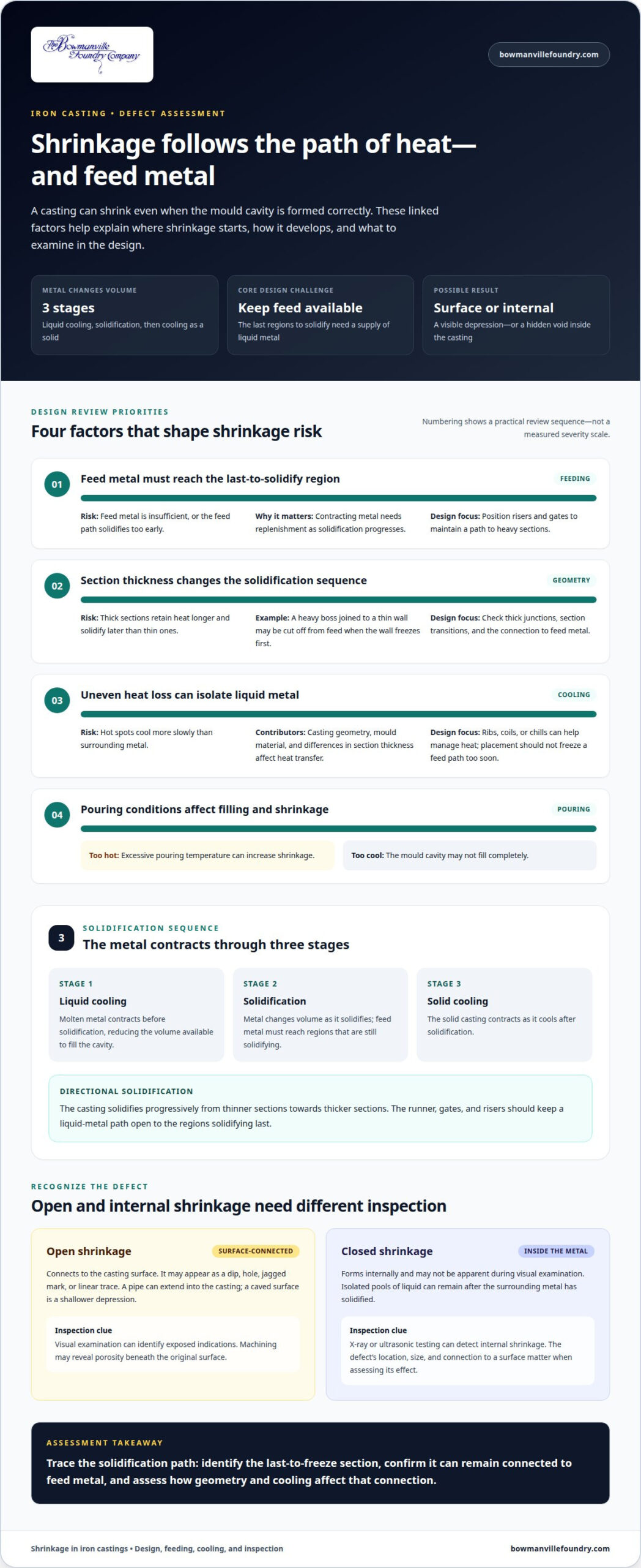
Iron changes volume in three stages: liquid metal contracts as it cools, changes volume during solidification, then contracts as the solid casting cools. The mould layout must account for each stage so feed metal can reach areas that are still solidifying.
Directional Solidification
Directional solidification means a casting solidifies progressively from its thinnest sections towards its thickest. This sequence matters because the last regions to solidify need a supply of liquid metal. For example, a thick junction between two thin walls may remain liquid after the walls have solidified. The gating and feeding layout should keep the junction connected to available feed metal as solidification progresses.
Thick Sections and Shrinkage Porosity
Shrinkage porosity forms when liquid metal cannot feed a region that contracts during solidification. Thick sections retain heat longer than thin ones, so they solidify later and may become isolated from the remaining liquid metal. A heavy boss joined to a thin wall is one example: the wall may freeze first, restricting feed to the boss. Section transitions and junctions therefore influence where porosity can develop.
Riser Design and Feeding
A riser, also called a feeder, holds liquid metal that can flow into the casting as it solidifies and contracts. Its position and connection to a heavy section matter: if the feed path solidifies too early, the riser cannot replenish the area that needs metal. A properly sized ingate and sprue attached to a heavy section can also support feeding. Together, the runner, gates, and risers should maintain a path to regions solidifying last.
What Is Shrinkage in Metal Casting?
Shrinkage defects form when molten metal contracts during cooling and solidification without enough feed metal. They may appear on the casting surface or remain hidden inside the metal.
Open and Closed Shrinkage Defects
Open shrinkage defects connect to the casting surface, while closed defects form inside the metal. This distinction matters because a visible cavity and a hidden void require different inspection approaches. An open defect may appear as a dip or hole; a pipe can extend into the casting, while a caved surface forms a shallower depression. Closed shrinkage can develop when isolated pools of liquid remain after the surrounding metal has solidified.
Surface and Internal Defects
Surface shrinkage may appear as a cavity, jagged mark, or linear trace, giving inspectors a visible area to assess. Internal shrinkage may not be apparent during visual examination. A hidden cavity can create a leak path or failure point under stress, so its location matters when evaluating a component for its intended service.
Inspection methods depend on whether the suspected defect is exposed or internal. X-ray or ultrasonic testing can detect internal shrinkage. Microporosity, also called microshrinkage, may appear as jagged marks or lines; magnification is needed to see its angular holes. These differences help distinguish surface indications from voids inside a casting.
Machining can expose porosity that was beneath the original surface, leaving blemishes or interruptions on a finished face. Internal cavities can reduce the continuous metal available to carry load, affecting strength and performance under stress. The defect’s location, size, and connection to a surface all influence its potential effect on service life.
In Canada, repair work depends on the defect’s accessibility and extent, as well as the part’s requirements. A surface cavity may be cleaned and assessed for repair, while internal shrinkage requires inspection to establish its location and reach. The appropriate response depends on whether the casting can meet its functional requirements after the defect is addressed.
Mould material and cooling rates
Moulds affect how quickly heat leaves molten iron, while casting geometry creates zones that cool at different rates. Pouring too hot can increase shrinkage; pouring too cool can prevent the mould from filling completely. Foundries manage risk by balancing pouring conditions, feeding, and cooling, then adjusting the mould or alloy where hot spots develop.
Shrinkage During Liquid Cooling
During liquid cooling, molten metal contracts before solidification, reducing the volume available to fill the cavity. If liquid iron cools unevenly, hotter areas can remain liquid after the surrounding metal begins to solidify. For example, a thick junction beside a thin wall may retain heat and continue contracting later. This temperature difference can contribute to shrinkage if metal cannot feed the area.
Mould material affects heat transfer at the casting surface and influences how quickly different sections lose heat. A sand mould around a broad, heavy section can retain heat differently from a thin section, which has more mould contact relative to its volume. The resulting cooling pattern matters because local temperature differences can isolate liquid regions before the casting has fully solidified.
Cooling Ribs, Coils and Chills
Cooling ribs, coils, and chills are mould features or inserts that help remove heat from selected regions. A chill near a hot spot can speed local cooling, while ribs can help distribute heat across a large casting area. Placement matters: the aim is to reduce uneven cooling without freezing a feed path before nearby metal has solidified.
Hot spots are regions that cool more slowly than surrounding metal because they contain greater volume. They can contribute to abnormal shrinkage, porosity, and cracks. For example, a bulky junction may remain hot after adjacent walls have hardened. Cooling practices or changes to the metal’s chemical composition can help address these areas.
Pouring Temperature and Cooling Rate
Pouring temperature and cooling rate affect both mould filling and the timing of solidification. Excessive pouring temperature can increase shrinkage, but a temperature that is too low can leave parts of the cavity unfilled. Faster cooling can also intensify shrinkage if solidification advances before enough liquid metal reaches contracting regions.
In grey iron, graphite formation expands during solidification and offsets some shrinkage. For ductile iron, foundries can assess the mould, feeding arrangement, cooling rate, and iron composition together. Chills can speed cooling in selected areas, while mould changes can address heat retention. The right balance depends on casting dimensions and the location of thick sections.
Casting shrinkage causes
Metallurgical review can help distinguish shrinkage from other graphite-related defects in ductile iron. Internal or surface discontinuities do not all have the same cause, so the defect’s shape, location, and graphite structure matter. For example, compacted graphite can indicate partly failed nodularisation, while exploded graphite and chunky graphite form under different conditions. Correctly identifying the defect keeps corrective action focused on the relevant process variable.
Excess rare earth metals can cause exploded graphite. They can also cause chunky graphite, which may occur in thinner casting sections and is less sensitive to carbon equivalent than exploded graphite. Elevated lead levels can produce spiky graphite; rare earths added with the nodulariser are cited as a way to address this defect. These graphite forms should not be mistaken for shrinkage porosity based on location alone.
Graphite distribution can also affect mechanical properties. Large dendrites growing during solidification can contribute to nodule alignment in ductile iron. That alignment can reduce tensile strength or impact resistance, even when shrinkage cavities are not the primary concern. Metallurgical evaluation therefore needs to consider both the defect’s appearance and the properties required of the finished component.
Carbides in ductile iron can result from poor inoculation, but inoculation is not the only possible cause. A useful investigation separates changes in graphite structure from shrinkage indications, then compares the findings with the casting’s production records. This distinction helps avoid treating every metallurgical anomaly as a feeding issue or changing mould design when the evidence points elsewhere.
For a casting-specific discussion of design and iron selection, discuss your iron casting requirements.
Bowmanville Foundry: Malleable Iron Castings
Bowmanville Foundry produces Malleable Iron Castings, Ductile Iron Castings, and Gray Iron Castings for manufacturers assessing material and casting requirements. If shrinkage concerns affect part design or grade selection, consider the casting geometry, intended service, and required properties together. These factors provide a useful starting point for discussing the casting.
For projects that require finishing after casting, Bowmanville Foundry offers Post-Processing Services. Sharing the part’s drawings, material requirements, and areas of concern can clarify what matters in the specification and production discussion.
Contact Bowmanville Foundry or visit bowmanvillefoundry.com to discuss your iron casting requirements.
Turn Casting Concerns into Clear Specifications
Understanding the causes of shrinkage in iron castings can help your team focus design and production discussions. Connect the concern to the component’s geometry, material requirements, and intended service. Note the affected area and gather relevant drawings, specifications, and inspection findings. These details provide a useful starting point for a technical conversation.
Bowmanville Foundry can discuss your iron casting requirements in relation to the part’s design and production needs. Sharing critical dimensions, inspection observations, and machining or finishing requirements helps define the questions that matter for your project.
Contact Bowmanville Foundry to discuss your casting requirements. A clear technical conversation is a constructive step towards defining your next project.
Frequently Asked Questions
What Causes Shrinkage Defects?
Shrinkage defects result from volume changes that leave a casting region without enough metal to maintain continuity. To investigate a defect, compare its position with the part drawing and production records. An indication recurring in the same feature directs attention to that geometry; changes between production runs make process records relevant. This evidence helps focus the review instead of treating every indication as the same problem.
What Type of Material Flaw Might Shrinkage Be Found In?
Shrinkage may be present as a discontinuity within the casting or at its surface. It is not a separate material or iron grade. For a component with critical machined faces, record the flaw’s position relative to those faces and the drawing. This context helps determine whether the indication intersects a functional area and makes inspection findings useful for design and production decisions.
What causes shrinkage defects in iron castings?
The causes of shrinkage in iron castings can be investigated by separating process evidence from material evidence. Start with the defect’s location and compare it with the part geometry and mould layout. Then review the relevant melt and production records for the same casting run. This sequence helps connect a specific indication to conditions associated with that part, rather than relying on a general diagnosis.
How do solidification shrinkage and liquid contraction differ in cast iron?
Liquid contraction occurs while iron remains molten; solidification shrinkage occurs as it changes from liquid to solid. The distinction is the stage when the volume change takes place. In an engineering review, identify whether the suspected area was still liquid or had begun freezing when feeding became restricted. This helps describe the defect mechanism precisely in design notes and production discussions.
How do iron composition, carbon equivalent, and inoculation affect shrinkage?
Composition, carbon equivalent, and inoculation are related but distinct parts of a metallurgical review. Chemistry records describe iron composition; carbon equivalent helps assess the combined influence of composition; inoculation records document a treatment that affects graphite formation. Comparing these records with the casting run gives engineers a more complete basis for interpreting a defect. A single chemistry value does not describe every condition involved in solidification.
What is the difference between shrinkage porosity, microshrinkage, and centerline shrinkage?
Shrinkage porosity is the broad term for voids associated with casting contraction. Microshrinkage describes a fine-scale form, while centerline shrinkage identifies porosity by its position near a casting’s centreline. The terms describe different aspects: general defect type, scale, and location. In an inspection report, recording both appearance and position makes the description more useful for comparing findings across parts.
