
A gear’s dimensions are only the starting point: material, accuracy, hardness and rim thickness all affect how it performs. In ductile iron gear manufacturing, ANSI/AGMA 6014-A06 recommends a minimum outer rim thickness of 4.5 times the module for steel and ductile iron gears. That relationship helps connect a design specification to the gear’s physical form.
Choosing a gear-making process means balancing the part’s geometry and service demands with how it will be produced. This article explains how cast and fabricated gear processes differ, and how dimensions, module, hardness, rim thickness and accuracy standards inform ductile iron gear decisions. You’ll find a practical framework for understanding these specifications and how they shape a custom gear design.
Key Takeaways
- Understand how casting and fabrication routes differ, and which production factors influence the choice for a custom gear.
- Learn how accuracy requirements affect gear specifications, manufacturing steps and fit in the intended application.
- See how dimensions, module and hardness inform material selection and gear design decisions.
- Explore how iron casting options, the Casting Buyers Guide and an engineer’s technical assessment can support your project.
Manufacturing Processes for Cast and Fabricated Gears
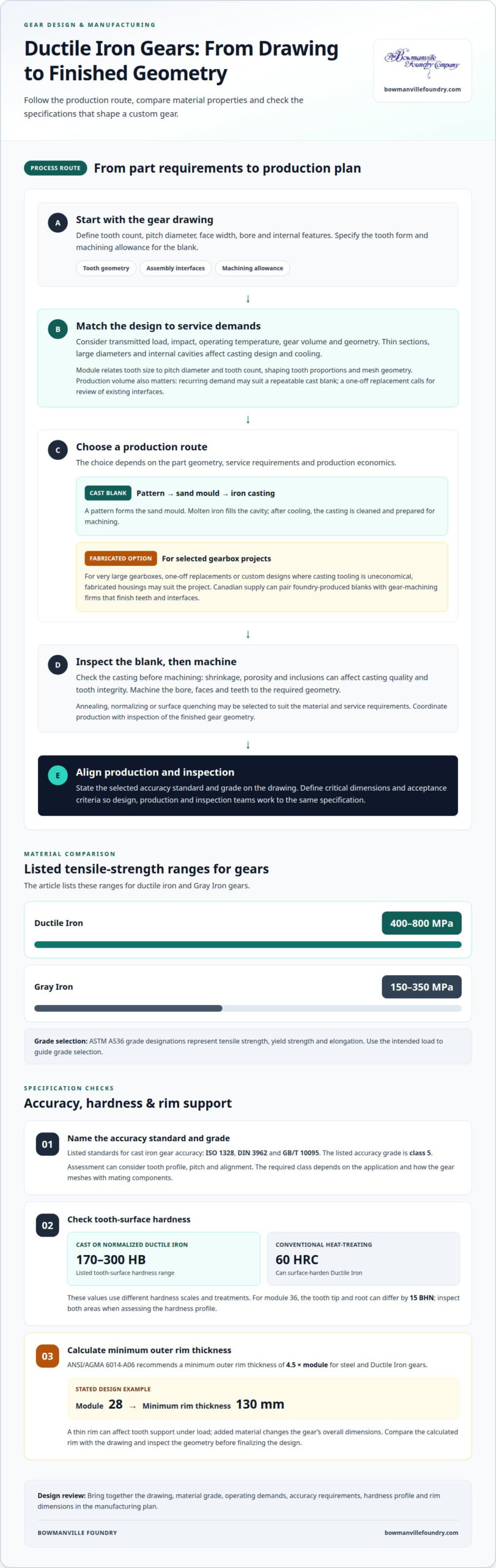
Ductile iron gear manufacturing starts with a drawing that defines the blank, tooth form and machining allowance. A pattern shapes a sand mould, molten iron fills the cavity, and the cooled casting is cleaned before machining. The machine then finishes the bore, faces and teeth to the required geometry. Annealing, normalizing or surface quenching may be selected for the material and service requirements.
Ductile iron gears have a listed tensile-strength range of 400 to 800 MPa, compared with 150 to 350 MPa for grey iron gears. ASTM A536 grade designations represent tensile strength, yield strength and elongation. These properties help engineers select a grade for the intended load. Shrinkage, porosity and inclusions can affect casting quality and tooth integrity, making blank inspection important before machining.
For very large gearboxes, one-off replacements or custom designs, fabricated housings may suit cases where casting tooling is uneconomical. Canadian supply can involve foundries producing blanks and gear-machining firms finishing teeth and interfaces. A ductile iron gear manufacturing plan coordinates those operations with inspection of finished geometry.
Gear Accuracy Standards
ISO 1328, DIN 3962 and GB/T 10095 are listed standards for cast iron gear accuracy. The listed accuracy grade is class 5. State the selected standard and grade on the gear drawing so production and inspection teams work to the same specification. The required class depends on the application and how the gear meshes with its mating components.
Accuracy assessment can consider tooth profile, pitch and alignment. These characteristics affect contact across the tooth face and how consistently the gear transmits motion. For a gear set, matching the specified accuracy across mating components helps the design meet its operating requirements. The specified grade also guides the manufacturing plan and inspection focus.
Define critical dimensions and gear characteristics alongside the chosen standard. For example, a drawing can identify the gear’s tooth geometry and the interfaces that determine assembly fit. Keep acceptance criteria clear across design, production and inspection. This makes accuracy requirements a usable part specification, rather than an isolated class designation.
Gear Dimensions and Modulus
A gear drawing should define tooth count, pitch diameter, face width, bore and internal features. Module relates tooth size to pitch diameter and tooth count, so it affects tooth proportions and mesh geometry. In ductile iron gear manufacturing, these dimensions guide pattern design and machining allowance. Establishing them early also clarifies shaft fit, mating clearances and which surfaces need finishing.
Material selection depends on transmitted load, impact, operating temperature, gear volume and geometry. Ductile iron’s strength and ductility can suit designs facing heavier loads than grey iron gears typically handle. Thin sections, large diameters and internal cavities affect casting design and cooling. Production volume matters too: recurring demand may suit a repeatable cast blank, while a one-off replacement calls for a design review focused on existing interfaces. A ductile iron gear manufacturing assessment brings these dimensions and service demands together to guide grade and process selection.
Gear Module, Hardness and Rim Thickness
Module defines tooth size, while hardness and rim thickness influence load capacity and wear resistance.
Hardness considerations
Cast or normalized ductile iron gears have a listed tooth-surface hardness range of 170 to 300 HB. Conventional heat-treating methods can surface-harden ductile iron to 60 HRC. These values describe different hardness scales and treatments, so compare each specification with the gear’s operating demands. Inspect the tooth surface and root, where contact and bending stresses affect components differently. For module 36, the tooth tip and root can differ by 15 BHN. That variation matters when assessing a suitable hardness profile.
Rim thickness considerations
ANSI/AGMA 6014-A06 recommends a minimum outer rim thickness of 4.5 times the module for steel and ductile iron gears. This relationship helps preserve support beneath the teeth. For example, a module of 28 requires a minimum rim thickness of 130 mm in the stated design example. Compare the calculated rim against the gear drawing and inspect the geometry before finalizing the design. A thin rim can affect tooth support under load, while added material changes the gear’s overall dimensions.
Ductile Iron Gear Castings
Bowmanville Foundry produces Ductile Iron Castings for manufacturers considering custom cast components, including potential gear blanks. Casting can suit projects where the geometry is cast first and then machined to the required interfaces. A technical assessment can consider the drawing, operating loads, bore, rim, tooth form and machining allowance before production planning.
Ductile Iron combines high tensile strength with good ductility. Bowmanville Foundry produces five grades of Austempered Ductile Iron, giving engineers material options to evaluate against application requirements. The foundry was the first in Canada to achieve ISO certification in 1996. Certification supports its quality management system, while each casting’s specifications remain tied to the part and intended service.
Post-Processing Services support finishing needs after casting. For gear-related projects, the review can consider how the blank’s form relates to the planned machining and finished-component requirements.
Gray Iron Castings
Gray Iron is often selected for industrial gearbox housings when vibration damping, dimensional stability and machinability matter. Its graphite structure helps damp vibration, making it useful when noise control is a design consideration. Grey iron gears are generally suited to low-speed, light-load service without impact; heavier loads or shock may call for a different material assessment.
For gear design, consider the load profile, tooth geometry, operating speed and required surface finish together. The listed tooth-surface hardness range for grey cast iron gears is 170 to 250 HB. That range provides a reference for evaluating wear requirements, but hardness alone does not determine suitability. Gear dimensions, mating components and operating conditions also shape the specification.
Bowmanville Foundry produces three grades of Gray Iron Castings. These grades give design and procurement teams options to assess against casting geometry and application needs. A drawing and clear service requirements help determine which grade is appropriate for a custom component.
Malleable Iron Castings
Malleable Iron is used for small castings that need good tensile strength and ductility. Its properties make it worth considering for compact components exposed to mechanical stress, where the design needs more flexibility than brittle iron can provide. Applications can include brackets, fittings and other small engineered parts, depending on the component’s load and geometry.
Production begins with a casting formed to the required shape, followed by heat treatment that develops the material’s final properties. Section thickness and component geometry matter because they influence casting design and heat-treatment response. Machining can then finish critical surfaces, holes or interfaces to suit assembly requirements.
Bowmanville Foundry produces Malleable Iron Castings for manufacturers evaluating iron materials for small components. A material decision should consider the part’s dimensions, loading, required ductility and finishing needs together. Where the application instead calls for larger castings or different strength and ductility characteristics, compare the design requirements with the other iron grades available for evaluation.
Free Casting Buyers Guide
The free Casting Buyers Guide from Bowmanville Foundry gives casting purchasers and design engineers a starting point for selecting an iron grade. It complements the foundry’s technical data and application guides, helping teams relate material choice to a component’s intended use. For a gear blank or other custom casting, grade selection should reflect loading, geometry and finishing requirements, not the material name alone.
Begin with the component’s function, drawing and service conditions. Note the required interfaces, section thicknesses and machining areas. These details frame a technical discussion about castability and material suitability. The guide can help organize early decisions, while application-specific data provides further context for comparing iron grades.
Procurement teams can use the guide to develop a shared specification with design engineers before production planning. Clear material requirements support a focused review of the part and its intended use. The guide is a practical reference for identifying the key questions in iron casting selection, without replacing engineering review of the component.
On-Site Technical/Sales Engineer Visit
An on-site technical assessment gives design and procurement teams a practical review of a casting application. Bowmanville Foundry’s technical/sales engineer can visit your facility to assess the part’s requirements and production considerations.
For a useful review, have the component drawing or CAD files available, along with key dimensions, service conditions and assembly interfaces. The assessment can consider geometry, section thickness, core requirements, machining allowances and the choice among Ductile Iron Castings, Gray Iron Castings or Malleable Iron Castings. If the project includes finishing, Post-Processing Services can also be discussed. These details connect the part design with casting feasibility and required finishing operations.
An on-site discussion is useful when a design is still being developed, a replacement component must fit existing equipment, or a drawing needs technical review before production planning. Contact Bowmanville Foundry to arrange an on-site technical/sales engineer visit.
Frequently Asked Questions
How are ductile iron gears manufactured, from casting to finished machining?
Manufacturing starts with a gear drawing that defines tooth geometry, bore, rim and machining stock. A pattern and sand mould form the blank. After casting and cooling, the blank is cleaned and its critical datums are machined. Teeth and interfaces are then finished to the drawing, followed by dimensional and tooth-geometry inspection. The material grade and any heat-treatment needs are selected to suit service loads.
What are the key design considerations for ductile iron gears?
Design begins with the load path and mating gear, then establishes module, tooth count, pitch diameter and face width. Assess the bore and shaft interface, mounting clearance and rim support as parts of the same assembly. For a replacement gear, existing shaft positions and available installation space constrain the design. Shock loading and operating environment also inform grade and geometry selection.
What gear-casting processes are used for ductile iron gears, and how do they affect quality?
Sand casting forms ductile iron gear blanks, with the pattern defining the cavity and the mould shaping the blank. Core placement, mould filling and solidification affect how consistently the casting reproduces the intended geometry. Inspecting the blank before machining can identify defects or excess stock that could affect finishing. Casting design also accounts for machining allowance at the teeth and interfaces.
What machining, heat treatment, and surface finishing do ductile iron gears require?
Machining establishes the bore, mounting faces and tooth geometry needed for assembly. Heat-treatment options include annealing, normalizing and surface quenching, selected to suit the material and duty. Surface treatments can include phosphating, oxidation and blackening, galvanizing or nickel plating. Because these operations serve different requirements, specify hardness, wear exposure and final interface condition to avoid conflicts with finished dimensions.
What tolerances, inspection methods, and quality standards apply to ductile iron gears?
Specify the applicable accuracy standard and grade on the drawing, then inspect the finished gear against its tooth and dimensional requirements. ISO 1328, DIN 3962 and GB/T 10095 are listed standards for cast iron gear accuracy; the stated grade is class 5. ASTM A536 specifies mechanical-property requirements, not tooth tolerances. Inspection should address tooth geometry, bore and critical mating dimensions.
What Canadian standards, safety rules, and environmental requirements apply to ductile iron gear production?
The listed gear-accuracy standards are ISO 1328, DIN 3962 and GB/T 10095; the drawing should state the selected standard and grade. The material provides no specific Canadian safety rules or environmental requirements.
