
Why do so many engineering projects accept excessive secondary machining as an inevitable tax on iron production? It’s a common frustration to see inconsistent dimensions across production runs or high scrap rates caused by tolerance stack-up. You likely realize that while sand casting is a foundational process, the gap between a rough part and a precision-engineered component often comes down to how you manage shrinkage across different iron grades. Achieving tight tolerances in iron casting isn’t just a matter of luck; it’s a coordinated engineering effort between pattern design, metallurgical control, and rigorous protocol.
This guide provides the technical foundation you need to master the variables required for high-precision iron components with repeatable accuracy. We’ll explore the latest ISO 8062-3:2023 standards and explain how Dimensional Casting Tolerance Grades (DCTG) influence your final output. By the end of this article, you’ll have a clear understanding of achievable casting limits and the knowledge to improve communication with your foundry team. This shift in approach helps you reduce secondary machining requirements and ensures your custom engineered components meet the exact specifications your application demands.
Key Takeaways
- Understand the updated ISO 8062-3:2023 standards to ensure your CAD specifications align with modern dimensional and geometrical tolerance grades.
- Discover how the physics of metal shrinkage and precision pattern engineering are the primary drivers for achieving tight tolerances in iron casting.
- Compare the dimensional stability of malleable, ductile, and gray iron to select the optimal material for your high-stress industrial applications.
- Learn to apply Design for Manufacturability (DFM) principles, including draft angles and uniform wall thicknesses, to promote consistent cooling and part accuracy.
- Realize the value of integrated machining and heat treating to deliver ready-to-use components that minimize internal scrap and secondary processing costs.
Understanding Dimensional Tolerances in Industrial Iron Casting
Casting tolerance represents the permissible deviation from a part’s nominal CAD dimensions. In industrial manufacturing, this variance accounts for the physical realities of the Sand casting process, where molten metal transitions from a liquid to a solid state. For high-stress Canadian industrial applications, such as heavy equipment or infrastructure components, dimensional precision is vital. Inaccurate parts lead to misalignments in complex assemblies, which can cause premature mechanical failure or safety risks in the field.
Distinguishing between as-cast and finished tolerances is a critical step in procurement. As-cast tolerances refer to the dimensions of the component exactly as it emerges from the mold, while finished tolerances are achieved through secondary machining. While machining provides the highest level of precision, achieving tight tolerances in iron casting at the as-cast stage significantly lowers the total cost of ownership. It reduces material waste and minimizes the labour hours required for post-processing, leading to more efficient assembly lines and lower per-unit costs.
Standard vs. Tight Tolerances: What is Realistic?
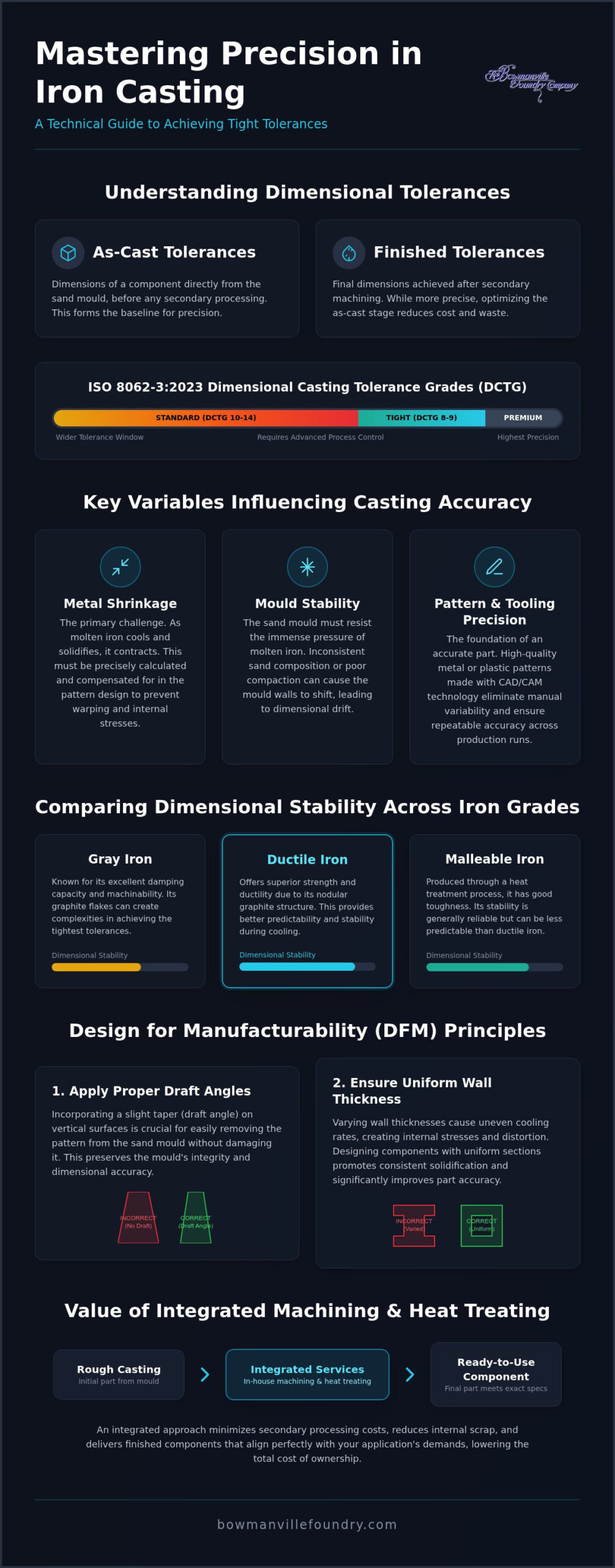
Commercial sand casting typically operates within a baseline defined by international standards like ISO 8062-3:2023. Most standard projects fall into Dimensional Casting Tolerance Grades (DCTG) 10 through 14. A project moves into the “tight” or premium category when specifications require DCTG 8 or 9. Realizing these tighter windows requires advanced pattern development and strict metallurgical control. Engineers should consult current ASTM standards to establish realistic baselines before finalizing designs. Over-specifying tolerances often inflates production costs without adding functional value, so it’s essential to align requirements with the actual mechanical needs of the application.
The Impact of Part Complexity on Precision
A component’s geometry and overall size directly dictate its achievable precision. As molten iron cools, it undergoes thermal contraction; larger parts experience more significant shrinkage, which naturally requires wider tolerance windows to account for the increased volume of moving metal. Complexity also introduces variables in cooling rates. For instance, a part with varying wall thicknesses will cool unevenly, creating temperature gradients that can lead to internal stresses and cooling-induced distortion. Standardizing wall thicknesses where possible promotes uniform cooling, which is a fundamental strategy for achieving tight tolerances in iron casting. Components with intricate internal cores or deep pockets also face higher risks of dimensional drift compared to simpler geometries due to the way heat is trapped within the mold.
Key Variables Influencing Iron Casting Accuracy
The physics of iron shrinkage represents the most significant challenge in maintaining dimensional accuracy. As molten iron transitions from a liquid to a solid state, it undergoes a predictable yet complex contraction. Engineers must account for this by applying a specific shrinkage allowance to the pattern design. If this contraction isn’t managed through precise thermal control, the resulting part may suffer from internal stresses or warping. Achieving tight tolerances in iron casting depends on your ability to stabilize the environment where this cooling occurs, ensuring the metal solidifies uniformly across all sections of the mould.
Mould stability is equally critical. The composition of the sand and the level of compaction directly influence how well the mould resists the static pressure of the molten iron. If the sand is too loose or the binder concentration is inconsistent, the mould walls may move slightly during the pour. This creates dimensional drift that is difficult to correct later. Engineers often refer to ISO 8062-3:2007 to establish baseline expectations for dimensional and geometrical tolerances, but reaching the tighter end of those scales requires a rigorous focus on sand integrity and flask rigidity.
Pattern Design and Tooling Precision
High-quality tooling serves as the foundation for any precision casting project. While wood patterns are suitable for low-volume prototypes, they’re susceptible to moisture and wear, which can degrade accuracy over time. For repeatable results, metal or high-density plastic patterns are preferred. Integrating CAD/CAM technology into the pattern-making process eliminates the variability of manual craftsmanship. This digital approach ensures that the “shrinkage allowance” is applied with mathematical precision across complex geometries. For projects requiring high-precision execution, reviewing a Free Casting Buyer’s Guide can help clarify these technical requirements during the planning phase.
Metallurgical Control and Pouring Temperature
The chemical makeup of the iron grade significantly affects both fluidity and shrinkage rates. Elements like carbon and silicon must be tightly controlled to maintain a consistent solidification range. If the chemistry fluctuates between batches, the shrinkage characteristics will change, leading to inconsistent part dimensions. Pouring temperature is another vital variable. If the iron is too hot, it increases the total thermal contraction; if it’s too cool, it may not fill the mould cavity properly. Maintaining a narrow temperature window is essential for ensuring that every part in a production run remains within the specified tolerance limits. Consistent monitoring of these metallurgical factors allows foundries to deliver components that meet strict engineering protocols without the need for excessive secondary machining.
Comparing Tolerances Across Malleable, Ductile, and Gray Iron
The internal carbon structure of an iron grade is a primary determinant of its dimensional stability. While the pattern sets the initial shape, the way graphite forms during solidification dictates how much the part will deviate from the nominal dimension. Engineers realize that achieving tight tolerances in iron casting involves matching the metallurgical properties of the metal to the physical requirements of the part. Gray iron, for example, contains graphite flakes that occupy more volume than the iron they replace. This volume increase effectively counteracts liquid-to-solid shrinkage, resulting in a material that is exceptionally stable for intricate, thin-walled designs.
Key material factors affecting tolerance include:
- Graphite Morphology: Flake graphite in gray iron provides the highest dimensional stability, whereas nodular graphite in ductile iron introduces expansion variables.
- Solidification Range: Different grades have varying cooling windows; longer ranges increase the risk of thermal distortion.
- Heat Treatment: Secondary processes like annealing or stress-relieving can cause slight dimensional shifts that must be anticipated.
Malleable Iron: Precision for Complex Hardware
Malleable iron requires a unique two-stage thermal process. It’s initially cast as white iron, which has a high shrinkage rate and is quite brittle. Through controlled annealing, the carbon is converted into temper carbon nodules. This provides a balance of ductility and strength, though the heat treatment introduces a variable for dimensional control. This material is excellent for complex hardware requiring high impact resistance, such as pipe fittings and electrical brackets. Mastering this transition is key to delivering high-precision components that withstand heavy mechanical stress. You can find more detail in The Comprehensive Guide to Malleable Iron Casting in Canada.
Ductile and Gray Iron: Stability in Heavy Industry
Gray iron is the standard for precision housings because its shrinkage is consistently low, around 1 percent. This predictability allows for thinner walls without warping. Ductile iron features nodular graphite that expands during solidification. While this reduces porosity, it creates a complex contraction profile. Achieving tight tolerances in iron casting with ductile grades requires rigorous mould rigidity to manage this thermal behaviour. Ductile iron’s higher strength is essential for structural parts, but the engineering team must account for these solidification dynamics to ensure dimensional repeatability. Selecting the right grade depends on balancing these thermal characteristics with the mechanical demands of the final application.
Design for Manufacturability: Strategies for Success
Design for Manufacturability (DFM) is the most effective way to control production costs while maintaining high precision. By optimizing a part’s geometry for the foundry environment, engineers can reduce the reliance on expensive corrective machining. Achieving tight tolerances in iron casting begins with implementing draft angles, typically between one and three degrees, which allow for clean pattern removal. Without sufficient draft, the pattern may drag against the sand, distorting the mould cavity and causing dimensional drift before the metal is even poured.
Standardizing wall thicknesses is another foundational DFM strategy. When a part features both heavy and thin sections, the thinner areas cool and solidify faster than the bulkier regions. This temperature imbalance creates internal stresses that lead to warping or “hot tears.” Using fillets and radii at every junction redistributes these stresses and prevents the sharp corners that often lead to dimensional shifting. Additionally, the strategic placement of parting lines ensures that flash is kept away from critical datum surfaces, minimizing the amount of finish grinding required to meet your specifications.
Optimizing Machining Allowances
Determining the correct machining allowance is a delicate balance between raw material volume and processing time. Under the ISO 8062-3:2023 standard, this is defined by Required Machining Allowance Grades (RMAG). Leaving too much “extra” material increases the weight of the casting and the wear on cutting tools; leaving too little risks failing to “clean up” the surface during machining. For a detailed breakdown of how to coordinate these phases, refer to our guide on Integrated Iron Casting and Machining in Canada. Proper allowance planning ensures that the final component matches the CAD model with absolute fidelity.
The Role of Heat Treating in Dimensional Stability
Heat treating is often the final step in securing dimensional stability, especially for ductile and malleable iron. Stress-relief annealing involves heating the casting to a specific temperature and cooling it slowly to “lock in” its dimensions. This process relieves the residual stresses built up during the initial cooling in the sand mould. By stabilizing the internal grain structure, heat treating prevents the part from “walking” or shifting during final precision machining. It also improves the machinability of the metal, allowing for smoother surface finishes and more accurate hole placements. Consulting with an engineering team during the design phase ensures your CAD models are optimized for the foundry floor. You can explore our custom engineered iron components to see how integrated design reduces total production costs.
The Bowmanville Approach: Custom Engineered Iron Precision
Operating since 1902, our foundry has spent over a century refining the technical variables required for high-precision manufacturing. We realize that achieving tight tolerances in iron casting is not a static goal but a dynamic process that requires deep institutional knowledge. Our expertise in custom engineered malleable, ductile, and gray iron castings allows us to guide Canadian industrial partners through the complexities of material selection and thermal management. By acting as a technical mentor rather than just a supplier, we ensure that every component is built on a foundation of metallurgical reality and physical craftsmanship.
Quality control at this level requires more than just visual inspection. We utilize advanced metrology and rigorous quality control protocols to prove accuracy at the micron level. This data-driven approach allows us to verify that our internal processes align with the latest international standards, providing you with the certainty needed for high-stress applications in sectors like railway infrastructure, oil and gas, and heavy machinery.
Collaborative Engineering for National Projects
Our collaborative engineering process starts long before the first pour. We work closely with your technical team to conduct a comprehensive CAD review, identifying potential dimensional risks such as uneven cooling or insufficient draft angles. By refining these designs early, we help you get the “as-cast” dimensions right the first time, which significantly reduces lead times for complex national projects. This proactive engagement ensures that your custom engineered components are optimized for the sand mould environment, preventing the distortion and internal stresses that often plague generic casting runs. We focus on creating a steady, knowledgeable partnership that prioritizes your project’s success through technical mastery.
Sourcing Ready-to-Use Components
One of the most effective ways to ensure dimensional integrity is to source ready-to-use iron components from a single, integrated provider. When you separate casting, machining, and heat treating across multiple vendors, you increase the risk of tolerance stack-up and communication errors. Our in-house pattern development and post-processing capabilities eliminate these variables. We provide fully machined, heat-treated, and inspected parts that are ready for immediate assembly. This integrated approach not only improves final accuracy but also reduces your internal scrap rates and administrative overhead. To learn more about optimizing your procurement process, you can Download our Free Casting Buyer’s Guide to start your next project with technical certainty.
Advancing Your Next Precision Engineering Project
Mastering the complex variables of shrinkage and mould stability is the first step toward reducing scrap rates and secondary machining costs. By aligning your CAD designs with established DFM principles and selecting the appropriate iron grade for your application’s mechanical needs, you create a predictable path for high-precision production. You likely realize that achieving tight tolerances in iron casting isn’t a matter of chance; it’s the result of a coordinated engineering effort between the design team and the foundry floor.
Since 1902, our foundry has specialized in malleable, ductile, and gray iron castings, providing the Canadian market with custom engineered components. We offer comprehensive post-processing services, including integrated machining and heat treating, to ensure your parts meet exact specifications without the risk of tolerance stack-up. Request a Custom Iron Casting Quote today to see how our technical expertise can bring repeatable accuracy to your most demanding industrial projects. We look forward to helping you navigate these intricate technical landscapes with confidence.
Frequently Asked Questions
What is the typical tolerance for a sand-cast iron part?
Typical tolerances for sand-cast iron parts generally fall within the Dimensional Casting Tolerance Grades (DCTG) 10 to 14 according to ISO 8062-3:2023. This equates to a variance of approximately plus or minus 0.5 mm to 1.5 mm depending on the nominal dimension. Achieving tight tolerances in iron casting below these levels requires high-precision metal tooling and strict control over sand density and pouring temperatures during the manufacturing process.
How does malleable iron shrinkage compare to ductile iron?
Malleable iron initially experiences higher shrinkage than ductile iron because it is cast as white iron before the annealing process. While ductile iron benefits from the expansion of nodular graphite during solidification, malleable iron requires a two-stage thermal cycle to achieve its final properties. This difference means that the pattern for a malleable part must account for more significant contraction to ensure the final component meets the required dimensional specifications.
Can I achieve CNC-level tolerances with as-cast iron?
You cannot typically achieve CNC-level tolerances, which often require precisions of 0.01 mm or less, with as-cast iron. While sand casting can produce highly accurate components, the physical nature of molten metal and sand moulds limits as-cast precision to broader windows. For applications requiring extreme accuracy, we recommend using integrated post-processing services where the casting is produced to a tight baseline and then finished through precision machining.
Why are draft angles necessary for achieving tight tolerances?
Draft angles are necessary because they facilitate the clean removal of the pattern from the sand mould without causing friction or dragging. Without a draft of at least one to three degrees, the pattern can disturb the mould walls, leading to dimensional inaccuracies or surface defects. Proper draft ensures the mould cavity remains an exact replica of the pattern, which is a fundamental requirement for achieving tight tolerances in iron casting.
How does heat treating affect the final dimensions of an iron casting?
Heat treating stabilizes final dimensions by relieving the internal residual stresses that develop during the initial cooling phase. Without stress-relief annealing, a casting might warp or shift when metal is removed during secondary machining. While the thermal cycle can cause minor growth or contraction depending on the iron grade, it ensures the component remains dimensionally stable throughout its service life in high-stress industrial environments across Canada.
What role does the pattern material play in dimensional repeatability?
Pattern material is the primary factor in ensuring dimensional repeatability over long production runs. Wood patterns are prone to warping due to moisture and wear, which leads to dimensional drift after only a few uses. In contrast, metal or high-density plastic patterns maintain their shape and surface integrity over thousands of cycles. This stability is essential for maintaining a consistent DCTG grade and reducing the need for corrective secondary processing.
How can I reduce the cost of achieving tight tolerances in my design?
You can reduce costs by implementing Design for Manufacturability (DFM) strategies like uniform wall thicknesses and generous fillets. These features promote even cooling and reduce the likelihood of distortion, which minimizes the amount of extra material required for machining allowances. Additionally, sourcing ready-to-use components from a single foundry with integrated machining capabilities eliminates the risk of tolerance stack-up and reduces the administrative costs of managing multiple vendors.
