
A CAD model’s volume is not the production weight. Calculating casting weight from CAD model volume gives a theoretical net part weight, not the amount of metal needed for a production pour.
The calculation is straightforward in principle: multiply the modelled metal volume by the density of the specified iron. The key is choosing a density that suits the material grade and keeping the units consistent. A generic density can make an estimate look more precise than it is.
This guide explains how to calculate theoretical net weight, which assumptions affect the result, and why it differs from production metal requirements. It also outlines which CAD files and material details help a foundry complete a technical assessment. Gating and risers guide molten metal and compensate for shrinkage during solidification. They are added during casting design and are not part of the finished component’s CAD volume. Understanding this distinction helps you interpret an estimate and prepare for a practical discussion about material selection and production requirements.
Key Takeaways
- For calculating casting weight from CAD model volume, multiply the model’s metal volume by the applicable density for the specified iron.
- Keep units consistent and record the material grade, density source, CAD file revision and assumptions behind the estimate.
- Separate finished-component weight from production metal requirements. Gating and risers are process features beyond the part geometry.
- Use the estimate as an early design and planning reference, not as a guarantee of final production weight or feasibility.
- Share CAD files and application requirements with a foundry engineer so the technical assessment can address material selection and casting design.
Why calculate casting weight from a CAD model?
A preliminary weight estimate helps design and procurement teams assess an iron component before its casting plan is established. It can inform decisions about handling, equipment needs, material selection and project planning. It is also useful for comparing design options, provided each comparison uses the same method and clearly recorded assumptions.
Definition: Theoretical net casting weight is the modelled volume of the finished metal component multiplied by the density selected for its material. Total production metal includes additional metal required by the casting process, so it is not the same as net part weight.
What does a CAD-derived casting weight represent?
The calculation begins with the component volume represented in the CAD files. That volume should describe the metal part being estimated, not an assembly containing unrelated components or spaces that are not part of the casting. Model completeness matters: missing features or geometry that differs from the intended cast component can change the volume and the calculated weight. When developing or reverse-engineering components from existing hardware, working with design and prototyping specialists such as FORMAQ Advanced Manufacturing can help ensure CAD models are fully accurate and production-ready.
Material selection matters too. Gray Iron, Ductile Iron and Malleable Iron have different material specifications, so use a density appropriate to the specified material rather than an unexplained generic value. The result is only as representative as its model and density inputs. It does not establish a foundry-approved production weight.
When is an early weight estimate useful?
During early project evaluation, design teams can use an estimate to see how a component’s geometry affects its mass. Procurement teams can use the same figure for preliminary planning while requirements are still being developed. For example, comparing two model revisions can show whether a geometry change increases or reduces the modelled part weight. That comparison is meaningful only if the material assumption and calculation method stay consistent.
Calculating casting weight from CAD model volume can also help frame material discussions. When comparing candidate iron materials, calculate each option using its applicable density and record the source. If the grade or model definition is still under review, label the results as estimates rather than exact values.
The estimate describes the component, not the complete metal charge for casting. A foundry determines process features such as gating and risers as part of casting design. These features direct molten metal and help compensate for shrinkage during solidification, but they are not finished-part geometry. The general principles are described in Casting (metalworking).
Use the estimate as an input to discussion, not as an approved production figure. Before making production decisions, have the foundry review the relevant CAD files alongside the specified material, component geometry and application requirements. A technical assessment can then consider casting suitability and process requirements that may affect the production plan.
How to calculate iron casting weight using CAD volume and density
The calculation is direct, but its inputs must be controlled: net weight = modelled metal volume × applicable material density. This gives the theoretical weight of the modelled component. It excludes gating, risers and other process metal that may be needed for production.
Check the units before multiplying. Volume and density must use compatible measurement systems. For example, convert a CAD volume reported in cubic millimetres if the density is expressed per cubic metre. Record the conversion instead of relying on an undocumented software setting or mental arithmetic.
Extract the correct volume from the CAD files
Use the CAD model’s solid metal volume, not the volume of its bounding box. A bounding box includes empty space around irregular geometry and can misrepresent the component. Confirm that holes, internal cavities, cores and separate model bodies match the intended cast part. Also note whether the model includes features such as machining allowance.
Record the model revision and the units reported by the CAD software. If an assembly contains several bodies, identify which belong to the component being estimated and whether they should be included together. A repeatable calculation measures the intended geometry rather than simply accepting the first volume value displayed.
Select density for the specified iron grade
Choose a technically appropriate density for the specified Gray Iron, Ductile Iron or Malleable Iron grade. A generic iron density is an assumption, not an exact value for every grade or specification. Record the density source and any assumptions with the result. The Estimated Casting Weight Calculation – odlewnictwo.pl reference also discusses the relationship between volume, density and estimated casting weight.
Illustrative calculation: If a hypothetical CAD model reports a volume of V cubic centimetres and the selected material data gives a density of D grams per cubic centimetre, the theoretical net weight is V × D grams. V and D are placeholders, not grade-specific values. For a real estimate, substitute the verified model volume and a density supported for the specified material.
Keep the calculation record clear enough for another engineer to reproduce. Include the CAD file revision, volume and units, specified iron grade, density value and source, unit conversions, and geometry assumptions. If the material specification does not provide a suitable density, flag the estimate as provisional rather than presenting a generic value as precise. Consistent inputs help design and procurement teams compare revisions without mistaking changes in assumptions for changes in geometry.
For an estimate that needs to inform casting design, discuss your CAD files and material requirements with a technical/sales engineer as part of a foundry technical assessment.
Net casting weight versus production metal: what the CAD estimate leaves out
A CAD-derived net weight describes the metal represented by the component geometry. A foundry’s production metal requirement also accounts for process features needed to fill the mold and produce a sound casting. Confusing these figures can lead to an estimate being used for a purpose it was not designed to serve.
Quotable distinction: CAD-derived net weight is the weight of the modelled component, not the pouring weight, because the model does not include the foundry’s gating and riser system.
| Weight measure | What it represents | What it excludes or depends on |
|---|---|---|
| Net casting weight | Metal volume represented by the component model multiplied by the applicable material density. | Production features not included in the component geometry. |
| Production metal requirement | Metal needed for the component and the process design used to cast it. | Depends on mold and process design, including gating and risers. |
Which weight belongs to the component itself?
Net casting weight refers to the modelled metal component, including its intended walls, holes and cavities. Those features affect the model’s volume and calculated net weight. The result also depends on what the CAD model represents. A finished machined part and a casting blank can have different geometries when material is allowed for later machining. Identify the model basis before treating its volume as the casting’s net weight.
Machining and other finishing operations happen after casting, but their effect on the weight estimate depends on the geometry supplied. If the model shows final machined dimensions, it may not include material needed on the casting before machining. The model’s volume is a calculation input, not a substitute for defining the required casting condition.
Why can production metal requirements differ?
During mold design, the foundry adds features to deliver molten iron to the cavity and compensate for shrinkage as the casting solidifies. Gating channels direct metal into the mold, while risers provide a reservoir of liquid metal. These features are removed from or remain separate from the finished component, so they are absent from its CAD geometry.
The amount and arrangement of process metal depend on the part, mold design and production method. The two-half mold, flask, mold compaction approach and component geometry all form part of the casting plan. There is no universal percentage or multiplier that reliably converts every net CAD weight into a pouring weight.
Use calculating casting weight from CAD model volume to establish the component estimate, then keep it separate from production metal requirements in project records. A foundry technical assessment of the CAD files and casting requirements provides the basis for a process-specific production estimate.
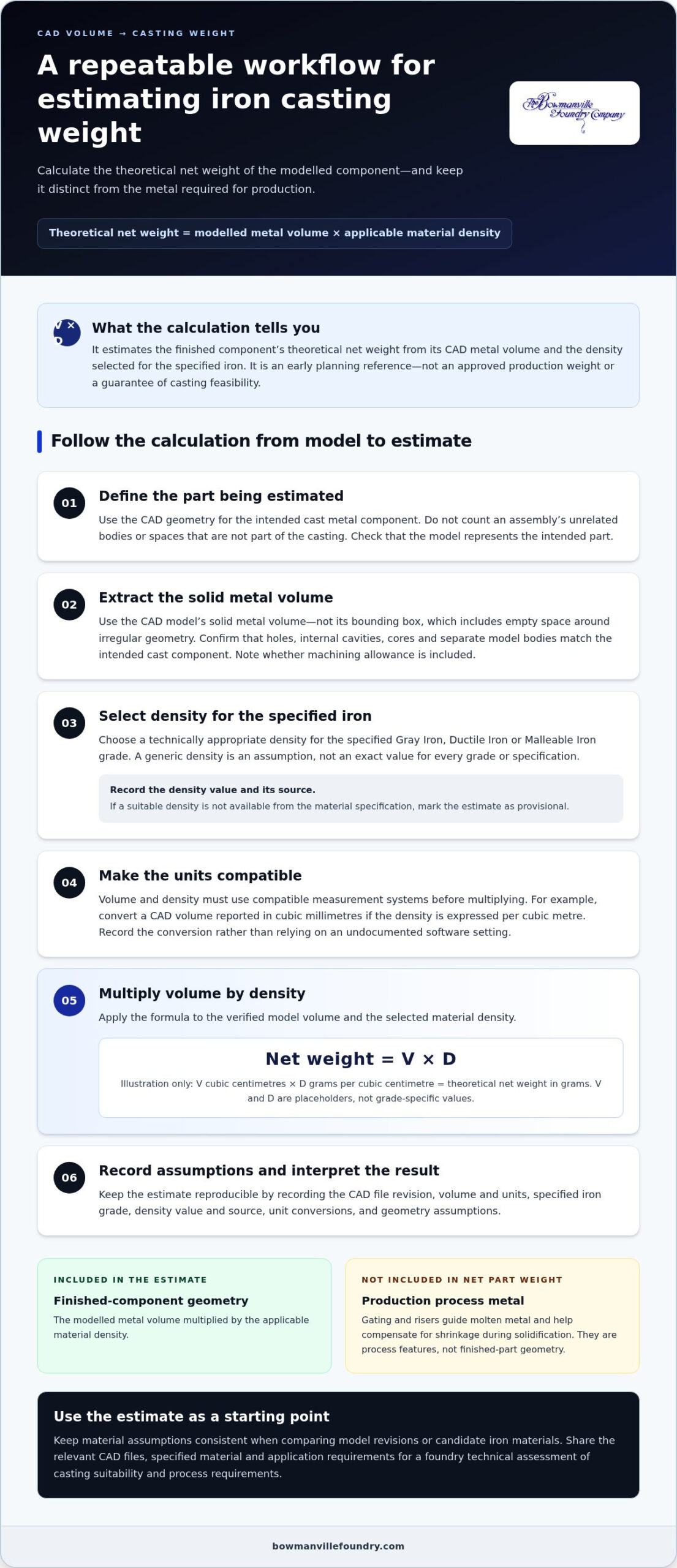
A repeatable workflow for estimating casting weight from CAD files
A documented method makes a weight estimate easier to check, update and compare. It also helps prevent changes in model revision, unit settings or material assumptions from being mistaken for changes in the component. Follow this sequence to keep the calculation traceable without treating it as a complete casting design.
Prepare model and calculation inputs
- Confirm the model revision. Check that the CAD files represent the intended component and production geometry. Record the file name or revision identifier, and whether the model shows the as-cast form or a later machined condition.
- Review the model bodies. Identify the solid bodies that make up the component. Check that holes and cavities are represented as intended and that unrelated assembly parts are not included in the reported volume.
- Record the volume and units. Capture the CAD system’s solid-volume result and its units. If you convert it, record the original value, conversion and resulting units so another person can reproduce the calculation.
- Specify the material input. Record the selected Gray Iron, Ductile Iron or Malleable Iron grade, along with the density value and its technical source. Do not substitute an unreferenced generic density for a grade-specific value.
- Flag details for review. Note cores, thin sections, machining requirements and other geometry that could affect interpretation of the model or its suitability for casting.
This check is especially useful when geometry is complex, the model contains multiple bodies, or the condition of a cavity or core is unclear from the supplied files. If CAD volume changes unexpectedly between revisions, verify the geometry and measurement method before updating the estimate. A manual model review may be needed to resolve ambiguous or incomplete geometry.
Document and interpret the estimate
Keep the calculation record with the model reference. Include the formula, volume and density inputs, units, conversions, density source, assumptions and resulting theoretical net weight. Retain appropriate input precision and round the reported result to a level supported by the inputs, rather than implying more accuracy than the model and density data allow.
For design comparisons, use the same measurement method and material assumption for each revision. If the grade or density source changes, record that change separately. Otherwise, a weight difference could reflect a changed input rather than changed geometry. Label the result as an estimate of modelled component weight, not a production metal requirement or approved pouring weight.
Use the record to support a focused foundry review of the part and its material requirements. Discuss your CAD files with a Bowmanville Foundry technical/sales engineer to arrange a technical assessment.
How a foundry technical assessment turns a CAD estimate into a casting plan
A net-weight calculation answers a limited question: how much the modelled component weighs under the selected material-density assumption. A foundry technical assessment considers the broader manufacturing requirements. Engineers review the CAD files alongside the material grade, geometry and intended application to determine whether the component can be produced as designed and what factors should inform a casting plan.
The estimate is one input to that review, not a production guarantee. A component’s weight alone cannot establish casting feasibility or determine the production metal required. The plan must account for how the part is formed and the requirements it must meet in service.
What a foundry engineer reviews beyond the weight estimate
In a technical assessment, the engineer considers how the design and its requirements relate to the selected iron and casting process. Relevant details may include:
- Material grade: The specified Gray Iron, Ductile Iron or Malleable Iron and the component’s stated functional requirements.
- Geometry: Wall transitions, sections, cavities and other features that affect how the part can be formed.
- Cores and mold design: Internal features may require cores, while the mold and production method shape the casting plan.
- Finishing requirements: Machining or other post-processing needs can affect the geometry and condition required from the casting.
These factors are considered together. For example, a cavity shown in the CAD files helps define the component, but the foundry must also assess how that feature will be created in the mold. The review connects a model-based estimate to practical manufacturing considerations without treating one weight figure as proof that the design is ready for production.
Discuss CAD files and requirements with Bowmanville Foundry
Bowmanville Foundry has produced iron castings since 1902 and serves customers across Canada. Its engineers can review your CAD files, material requirements and application as part of a technical assessment. Sharing the intended model revision and relevant functional requirements helps focus the review on the component and its use.
Bowmanville Foundry was the first foundry in Canada to achieve ISO certification in 1996. This history reflects the foundry’s quality-focused approach, while each technical assessment remains specific to the part, material and project requirements.
For additional design context, the iron casting design guide covers considerations that can inform a casting project. To discuss a model and its requirements directly, contact Bowmanville Foundry to arrange a technical assessment with a technical/sales engineer. The review can connect the theoretical estimate to material selection and manufacturing feasibility.
Move from estimate to engineering review
Bring the weight estimate into the same discussion as the component’s intended function and design priorities. This gives design, procurement and foundry teams a shared basis for considering material selection and manufacturing feasibility before project requirements are finalized. Keep the assumptions visible so an engineer can distinguish model changes from changes to the selected material data.
Gather the relevant CAD files, model revision, specified iron grade and application requirements for that discussion. This information helps a technical/sales engineer understand the component in context and identify questions that a weight figure alone cannot answer. Calculating casting weight from CAD model volume is a practical starting point; the next step is applying engineering judgement to the specific part.
Discuss your CAD files and casting requirements with Bowmanville Foundry to arrange a technical assessment and move from an early estimate towards an informed casting plan.
Frequently Asked Questions
Can you calculate casting weight from a CAD model?
Yes. You can calculate casting weight from CAD data when the CAD system can report reliable mass properties for the intended component. In a solid-modelling program, check the material assignment and active configuration before accepting a mass result. An unassigned material or an assembly configuration can produce a misleading output. Treat the software result as a preliminary engineering value and label its basis clearly in design reviews and procurement records.
Does CAD volume include holes and internal cavities in a casting?
A CAD volume reflects only the bodies and features active in the selected model configuration. Check whether the file contains multiple solids, reference geometry, suppressed features or assembly components that should not be included. For a section formed with a core, compare the intended internal form with the drawing or design definition. This helps distinguish a genuine casting feature from an incomplete or display-only model feature.
Does a CAD-derived weight equal the final casting weight?
No. The model-derived value is not a verified measurement of a physical casting. If mass is a controlled design requirement, define the condition in which the component should be weighed, such as before or after specified machining, and align that basis with inspection records. A production sample can then be compared with the estimate under the same stated conditions, helping identify whether a difference relates to geometry, finishing or material assumptions.
What if the CAD model volume and density use different units?
Use the CAD system’s unit settings or a controlled calculation sheet to manage the conversion, then have a second reviewer check the result before it enters a specification. As a plausibility check, consider whether the reported weight makes sense for the component’s physical size and intended application. Save the original CAD volume output with the calculation record so a reviewer can trace the inputs.
Can a CAD model predict the exact weight before an iron grade is selected?
No. Until the material grade is selected, the model cannot provide a grade-specific mass result. Shortlist candidate grades against the component’s required mechanical performance, wear conditions and service environment, then treat weight comparisons as preliminary. A technical discussion can help separate essential material requirements from design preferences, so mass comparison is not used as the sole basis for selecting a grade.
What information should I provide for a casting weight assessment?
Along with the model, explain what decision the assessment should support, such as material selection, a geometry change or review of a weight target. Identify critical mating interfaces, load-bearing regions and service conditions that constrain the design. If the team is comparing versions, point out the preferred candidate and unresolved questions. This context helps the engineer focus on the design intent.
