
A riser in the wrong place can leave shrinkage in the section it is meant to feed. Effective gating and risering system design places risers at heavy sections expected to solidify last, sizes them to feed metal contraction, and controls molten metal flow into the mould. Alloy behaviour matters because different irons respond differently during filling and solidification.
Riser size is only one part of the design. Placement, feeding distance, gate location and pouring practice work together. A sound system guides metal through the mould, supports directional solidification and limits turbulence, gas entrapment and impurities.
This guide explains how to assess casting geometry, choose riser locations, account for alloy behaviour and refine pouring practices. It also shows how to trace shrinkage, porosity, cold shuts and mould erosion to likely process causes, keeping the full casting sequence in view when making design decisions.
Key Takeaways
- Use a pouring basin and skim bob to help keep impurities out of the mould cavity, and manage flow to limit turbulence.
- Size risers to feed metal during solidification and support directional feeding as the casting contracts.
- Place risers at heavy sections expected to freeze last; divide complex castings into feeding zones when needed.
- Account for alloy behaviour when refining the gating layout, pouring practice and troubleshooting approach.
Pouring practices, defects and troubleshooting
In Canada, follow the occupational health and safety requirements that apply in your province or territory, along with the foundry’s molten-metal procedures. Gating design is a casting-process decision, not a substitute for workplace controls.
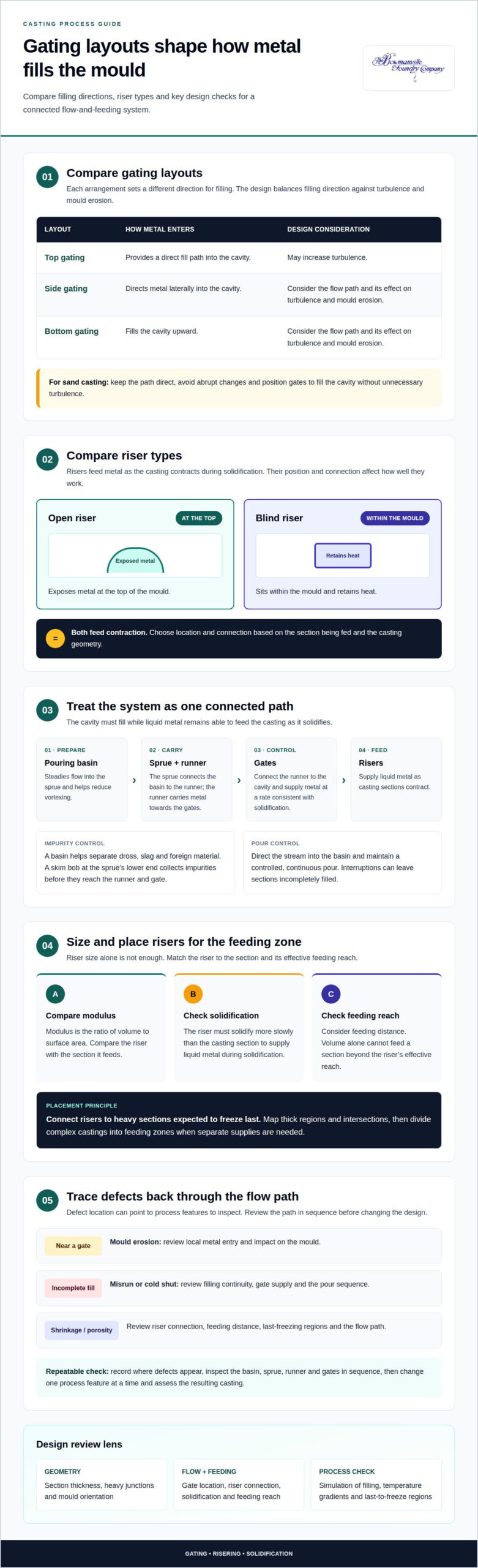
- Keep the metal path clear. A gating system guides molten metal into the mould through a connected flow path. Use the basin to help separate dross, slag and foreign material before metal enters the sprue. A skim bob at the sprue’s lower end collects impurities before they can travel through the runner and gate into the mould cavity.
- Control entry into the mould. The sprue connects the basin to the runner, while the runner carries metal towards the gates. Arrange this path to limit turbulence and gas entrapment. The gate connects the runner to the cavity and should supply metal at a rate consistent with the casting’s solidification. Poor flow control can contribute to oxidation, cold shuts or misruns.
- Match the pour to the gating layout. Keep the stream directed into the pouring basin and maintain a controlled, continuous pour. A basin helps maintain the required flow rate and reduces turbulence and vortexing at the sprue entrance. Avoid interruptions that can leave sections incompletely filled, creating misruns or cold shuts. Review the pour sequence alongside the gate locations.
- Trace defects to process causes. Improper gating can contribute to mould erosion, shrinkage, porosity and penetration of liquid metal into mould walls. Compare defect location with the runner, gate and cavity flow path. For example, erosion near a gate points attention to local metal entry and mould impact; a misrun calls for review of filling continuity and gate supply.
- Use repeatable troubleshooting checks. Record where each defect appears, then inspect the basin, sprue, runner and gates in sequence. Check for trapped impurities, turbulent flow paths and inconsistent filling. Gating design affects casting quality and yield, so change one process feature at a time and assess the resulting casting before revising other parts of the system.
Riser function in shrinkage compensation
Design the pouring basin, runner, gates and risers as one flow and feeding system. The system must fill the cavity while maintaining a path for liquid metal as the casting solidifies.
-
Choose a gating arrangement and basin function
Use the pouring basin to steady flow into the sprue and reduce vortexing at its entrance. The runner carries metal to the gates, which control its entry into the mould cavity. Top gating provides a direct fill path but may increase turbulence; side gating directs flow laterally, while bottom gating fills the cavity upward. Each layout balances filling direction against turbulence and mould erosion.
In sand casting, keep the flow path direct, avoid abrupt changes and position gates to fill the cavity without unnecessary turbulence. Open risers expose metal at the top of the mould, while blind risers sit within it and retain heat. Both feed contraction, but their position and connection affect how well they work.
-
Size risers using feeding measures
Size the riser by comparing its modulus, the ratio of volume to surface area, with that of the section it feeds. The riser must solidify more slowly than the casting section so it can supply liquid metal during solidification. Also consider solidification time and feeding distance: volume alone cannot feed a section beyond the riser’s effective reach. Connect the riser to the last-freezing region and avoid long, narrow feeding paths.
-
Use simulation to predict shrinkage
Model filling and solidification to compare gate locations, runner paths, riser dimensions and connection points before producing the mould. Review predicted flow, temperature gradients and last-to-freeze regions for potential shrinkage defects. Use the results to compare options, then align the chosen layout with the casting geometry and foundry process.
For iron grade selection that informs casting decisions, the Free Casting Buyer’s Guide provides a practical next reference.
Riser placement based on casting geometry and process
Map thick sections, thin walls and mould orientation before setting riser locations. The casting’s shape, size and position determine how metal can feed each region during solidification.
Assess casting geometry and process
Identify changes in section thickness and the heavy regions likely to stay hot longest. A thick junction beside a thin wall can solidify differently, so assess each region rather than treating the casting as uniform. Include mould orientation and process layout, which affect riser connections and how metal reaches the casting.
- Mark likely last-freezing areas. Trace thick sections, intersections and concentrated masses on the casting drawing. Treat these as candidate feeding zones, then consider whether their connections allow liquid metal to reach them.
- Divide complex geometry into zones. For a large, complicated casting, identify areas that may need separate risers. Set zone boundaries around the effective feeding range of each riser, avoiding gaps that could leave a region without a feeding path.
Determine riser placement and location
Attach each riser to a heavy section expected to solidify last, positioning the connection to feed that region. Consider the riser’s location in the mould as well as the casting’s shape and size. Do not choose a location solely for convenient access: a remote or obstructed connection may not feed the intended section effectively.
- Match risers to feeding zones. Assign a riser to each zone that needs its own supply of molten metal. For example, a casting with separated heavy regions may require multiple risers, each serving its own effective feeding range.
- Review the connection path. Check the route from riser to target section for narrow or interrupted transitions. Keep the connection aligned with the region it must feed, and assess whether the mould layout permits that placement.
- Reassess after orientation changes. If the casting or mould position changes, review which sections solidify last and where risers can connect. Confirm that each zone remains fed by a suitably located riser.
Alloy effects on riser and gating design
Select the alloy before finalizing the feeding layout. Graphite form, grade and casting geometry all affect how metal fills and solidifies.
- Identify the iron family and grade. Gray Iron contains flake graphite, while Ductile Iron has nodular graphite; Malleable Iron develops its structure through heat treatment. These differences mean a layout suited to one iron cannot automatically be transferred to another. Use the selected grade and section geometry as inputs to the design.
- Review filling behaviour before setting gates. Assess how the chosen alloy flows through the runner and enters thin walls, junctions and heavier sections. A gate that fills one geometry smoothly may cause turbulence or incomplete filling elsewhere. For example, a long, thin passage needs a suitable metal supply before the adjoining thick region begins solidifying.
- Reassess feeding for the alloy and section. Riser performance depends on the casting’s solidification pattern, not alloy name alone. Consider the grade alongside section thickness, riser connection and expected last-to-freeze regions. Avoid carrying over riser dimensions from another alloy without reviewing whether the riser remains liquid long enough to feed contraction.
- Keep the design tied to the production process. In gating and risering system design, evaluate the alloy, mould layout and pour as one system. A change in grade can alter filling and solidification behaviour, so review gate locations, riser connections and feeding zones together. Use casting results to identify whether a defect relates to flow, feeding or local geometry.
- Document alloy-specific revisions. Record the selected grade and the reason for each change to gates or risers. Compare outcomes across castings made to the same geometry and process. This helps distinguish an alloy-related response from a mould-layout or pouring variation, and gives future revisions a clear technical basis.
For help selecting an iron grade for your application, discuss your casting requirements.
Bowmanville Foundry
Bowmanville Foundry can help bring iron grade selection and casting requirements together. Its malleable, ductile and grey iron castings suit different material needs, so the intended application and part geometry provide a useful starting point. When discussing a project, share the casting’s function, key sections and production requirements to give the specification discussion practical context.
For parts that need finishing, Bowmanville Foundry also provides post-processing services. The foundry can support development of a new casting or review of an existing iron part, particularly when material choice and downstream processing affect the specification. Contact Bowmanville Foundry to discuss your casting requirements.
Carry design decisions into production
Effective gating and risering system design takes more than a drawing. Treat each revision as a recorded engineering decision: connect the selected alloy and casting geometry to the feeding strategy, then document which production observations prompt changes. This gives design and procurement teams a shared basis for discussing the specification and evaluating future revisions.
As you move from a part concept to a production requirement, identify the material, critical geometry and finishing needs that shape the specification. Bowmanville Foundry can help with iron casting requirements and related finishing. Contact Bowmanville Foundry to discuss your casting requirements.
A clear technical discussion is a practical next step toward a casting specification suited to your application.
Frequently Asked Questions
What are the basic principles of gating and riser system design in metal casting?
Start with a controlled design sequence: establish the casting drawing, selected alloy, mould method and acceptance requirements before laying out the system. Record design assumptions so production results can be compared with the intended process. If a trial casting shows a recurring issue, change one design variable at a time. That makes each revision’s effect easier to assess and document.
How do you calculate gating ratios and pouring basin, sprue, runner, and ingate dimensions?
Use the required metal volume and planned filling time to establish a target flow rate, then choose a gating ratio suited to the process. Dimension the controlling restriction first, then size the basin, sprue, runner and ingates around the flow path. Account for metal head and changes in passage size, since abrupt transitions can affect delivery. Check dimensions against the mould layout and production observations.
How does gating and riser design differ for aluminium, iron, steel, and copper alloys?
Each alloy family needs design inputs that reflect its filling and solidification behaviour. Avoid applying one gating ratio or riser arrangement to aluminium, iron, steel and copper jobs alike. For iron castings, identify the specified grade rather than treating all iron as the same material. Record alloy and process assumptions with the casting design so later revisions remain specific to the job.
How do casting geometry, wall thickness, and alloy shrinkage affect riser placement and size?
Use the part model to identify section transitions, core intersections and practical riser attachment surfaces. A core can create local thermal conditions that differ from an open section, while an attachment may interfere with a machined face or assembly feature. Include these constraints when choosing attachment locations. Preserve functional surfaces and account for how the mould can be made and cleaned.
What are common gating and risering defects, their causes, and prevention methods?
Identify defects by their appearance and location before changing the process. Rounded pores differ from a concentrated shrinkage cavity, while a surface fold or incomplete joint may point to a filling issue. Record the defect’s position, shape and frequency, then compare it with the casting drawing and process record. This evidence helps target a correction without changing several system features at once.
