
Even a well-made sand core can shift during pouring if the mould does not locate and support it properly. Core prints in sand casting are recesses in the mould that position and support the core, helping resist the upward buoyancy created when molten metal surrounds it. Their design affects whether internal features remain in position and whether the core can be removed after solidification.
Core-print design matters when a casting needs accurate internal passages, controlled wall thickness or clean openings. The core must withstand handling and pouring, let gases escape, and break down enough for removal without damaging the casting.
This article explains how core prints support and release cores, how sand cores are made and inspected, and how strength, permeability and collapsibility affect casting results. It also covers common core-related defects and the drawing and inspection details that help engineers and casting buyers assess cored features.
Key Takeaways
- For complex internal geometry, multiple cores can be assembled into a core package; their arrangement affects passage shape and wall-thickness control.
- Binder type, sand grain size, coating, venting and storage conditions all influence core performance and the finished casting.
- Inspection may combine dimensional checks with methods such as borescope, pressure or leak testing, X-ray or CT, depending on the feature.
- Mark critical internal features on the drawing and include passage geometry, cleaning access and inspection requirements in the casting RFQ.
Core classifications and types
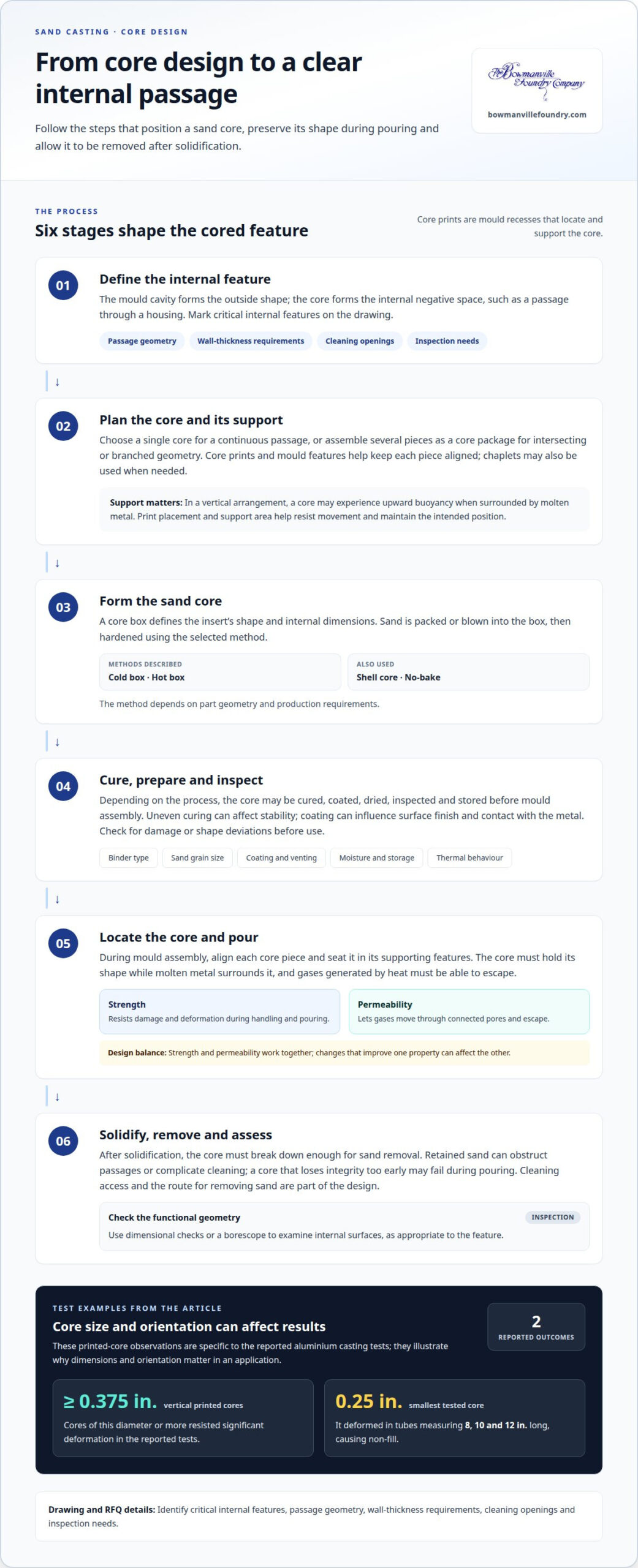
A core is a hardened sand insert that forms a hollow section or other internal feature in a casting. The mould cavity defines the outside shape, while the core forms the internal negative space. For example, a core can create a passage through a housing that would otherwise fill with metal. Core prints are recesses in the mould that locate and support these inserts, linking internal geometry to the mould design.
Core configurations range from a single insert to several pieces assembled as a core package. One core can form a continuous passage, while a package can create intersecting or branched internal geometry. The foundry must keep each piece aligned during mould assembly, since a mismatch can affect passage position and the surrounding wall thickness. Core prints and mould features provide support; chaplets may also be used when needed.
Core prints are shaped to receive the ends or bearing areas of a core. Their placement depends on the core’s orientation and the forces acting during pouring. In a vertical arrangement, the sand core may experience upward buoyancy because it is less dense than molten metal. The prints help resist this movement and maintain the intended position. Their design also depends on the moulding sand, which affects how the support area carries the load.
For a complex casting, the core plan should match the drawing’s internal features and provide access for cleaning. Cored passages need openings or access paths so sand can be removed after solidification without damaging the part. Inspection can focus on functional geometry, using dimensional checks or a borescope to examine internal surfaces. In an RFQ, mark critical internal features on the drawing and specify passage geometry, wall-thickness requirements, cleaning openings and inspection needs. These details connect core design to the finished part’s function.
Core strength, permeability, and collapsibility
A core must hold its shape during handling and pouring, let gases escape, and then break down after solidification. These properties affect internal geometry, casting quality and the effort required for cleaning.
Core strength
Core strength is the ability of hardened sand to resist damage and deformation during handling and pouring. Core sand needs higher strength than moulding sand because molten metal surrounds it under severe thermal and mechanical conditions. If a core cracks or shifts, an internal passage may be distorted or blocked. Printed-core tests in aluminium casting found that cores with diameters of 0.375 in. or more resisted significant deformation when positioned vertically. This result illustrates why core dimensions and orientation matter in specific applications.
Core permeability
Core permeability is the ability of sand to let gases pass through its connected pores. Heat during pouring can generate gases in the core; if they cannot escape readily, gas-related defects may form in the casting. Permeability must therefore suit the core geometry and binder system. A narrow or long internal passage may restrict venting, while the sand and core design affect gas movement. Foundry production balances permeability with strength, since changes that improve one property can affect the other.
Core collapsibility
Core collapsibility is its ability to break down after the metal has solidified. It matters because retained sand can obstruct passages, complicate cleaning or damage thin internal features during removal. A core that resists breakdown too strongly can make shakeout difficult; one that loses integrity too early may fail during pouring. The right balance depends on the casting geometry, metal conditions and cleaning access. A long enclosed passage, for example, needs stable support before solidification and a practical route for removing sand afterward.
These properties work together rather than independently: sufficient strength preserves position, permeability vents gases, and collapsibility supports removal. Printed aluminium test castings showed that the smallest, 0.25-in. core deformed in tubes measuring 8, 10, and 12 in. long, causing non-fill. For iron components, selecting the material and core design together helps define functional internal features. Explore Ductile Iron castings when material selection is part of the design decision.
Sand core manufacturing methods
Sand core manufacturing starts with a core box that defines the insert’s shape and internal dimensions. The process depends on part geometry and production requirements. Cold box, hot box, shell core and no-bake methods form cores using different combinations of sand and binder. The method affects handling strength, gas release, surface finish and cleaning after casting.
During manufacture, sand is packed or blown into the core box, then hardened using the selected process. The core may be cured, coated, dried, inspected and stored before mould assembly. Each stage can affect dimensional accuracy: uneven curing can change core stability, while coating can influence surface finish and contact with the metal. Inspection before storage helps catch damage or shape deviations before the core reaches the mould.
Core-box design also affects how consistently the sand forms the intended geometry. Parting lines, vents and core ends must support formation and later placement. For example, very small 4 mm cores may be reinforced with a wire through the middle. This can help the slender insert withstand handling. The method and box details depend on the feature’s dimensions and the core’s role in the casting.
Manufacturing variables affect defects and downstream work. Binder type, sand grain size, coating, venting method, moisture control, storage conditions and thermal behaviour can influence gas defects, surface finish, core erosion and cleaning difficulty. For a long internal passage, venting and sand removal are important design considerations. The foundry aligns these process choices with the part’s internal geometry and inspection needs.
- Cold box: A core-making method selected according to the part and production requirements.
- Hot box: A method in which the process hardens sand in the core box.
- Shell core: A method used to form a sand core in a shaped box.
- No-bake: A method suited to core requirements defined by the casting design.
Whatever the method, dimensional checks should focus on the features that locate the core and define functional passages. Coating, drying and storage must preserve those features until mould assembly. Clear drawings of internal geometry help coordinate core-box design, manufacturing and inspection.
Core prints in sand casting
Core-print design determines how a sand core is located and supported during metal casting. Dimensions must suit the core, the moulding sand and the forces expected during pouring.
Core prints and chaplets
Core prints are mould recesses that seat and support a core. Chaplets are separate supports used when mould features alone cannot hold it in position. Prints rely on the surrounding mould, while chaplets provide support at selected contact points. For Canadian casting projects, design is based on the part drawing and the foundry’s process-specific engineering criteria. Print size depends on the moulding sand and the forces acting on the core.
Common defects and prevention
Poorly designed core prints can contribute to core shift or breakage, resulting in misplaced passages or poor wall-thickness control. Sand inclusion, metal penetration and rough internal surfaces are other defects associated with cored features. Prevention starts with matching print geometry to the core ends and ensuring the bearing surfaces support the expected load. A dimensional review of the assembled mould can identify misalignment before pouring; inspection plans can then focus on critical internal features.
Risks from loose cores
A loose or poorly supported core can move or break under the thermal and mechanical conditions of pouring. The casting may then have blocked passages, incorrect internal dimensions or uneven walls, requiring further assessment or rejection. Core movement can also disrupt metal flow and compromise mould integrity, creating potential exposure to hot metal for personnel near the pour. Secure prints, suitable chaplets when needed and a checked mould assembly help control these process hazards.
For an iron casting, review core support alongside passage geometry, cleaning access and inspection needs. Discuss core-print design as part of your casting requirements.
Bowmanville Foundry: Free Casting Buyer’s Guide
Bowmanville Foundry’s Free Casting Buyer’s Guide helps casting buyers assess iron grades for their applications. For a cored component with critical internal passages, consider the casting’s function alongside material selection and finished-feature requirements. The guide supports decisions among Gray Iron, Ductile Iron and Malleable Iron. Bowmanville Foundry also offers post-processing services for castings that need further work.
For a project with defined internal geometry, drawings and inspection requirements provide a useful basis for discussing the casting. Contact Bowmanville Foundry to discuss your iron casting requirements.
Carry the core design into your casting decision
As a casting design moves toward production, turn internal-feature requirements into clear drawing callouts and acceptance criteria. This gives engineering and procurement teams a shared basis for reviewing functional dimensions, access and inspection. Treat core prints in sand casting as one part of the broader design review, linking the mould plan to the finished component’s requirements.
For your next design review, assemble the relevant drawings and identify which internal features affect function. A focused discussion can help clarify the information needed to assess the casting. Contact Bowmanville Foundry today to discuss your project and determine a practical next step.
Frequently Asked Questions
How are sand cores removed and inspected?
Removal methods include shakeout, mechanical cleaning and water-assisted cleaning; the binder and casting geometry determine the suitable approach. Inspection can target specific concerns: a borescope examines inaccessible internal surfaces, while CMM checks assess dimensions. Pressure or leak testing evaluates passage integrity. X-ray, CT or sectioning can assess internal conditions when surface access alone is insufficient.
How do sand cores create internal passages?
Core geometry is defined in the casting design and carried into the core-box and mould plans. For an RFQ, provide internal passage geometry, wall-thickness requirements, machining allowance and cleaning openings. Mark critical internal features as functional on the drawing. This gives the foundry a basis for reviewing core design, mould assembly, cleaning access, machining plans and the inspection evidence required for the part.
What core properties matter for cast metal parts?
Strength, permeability, dimensional stability and collapsibility all matter, but the drawing should also state how the finished feature will be assessed. A pressure-carrying passage, for example, may need a leak test, while a machined bore needs dimensional inspection. Binder, sand grain size, coating, venting, moisture and storage can affect defects and cleaning. Relate these process factors to the part’s acceptance requirements.
What is a sand core in sand casting?
A sand core is a shaped insert made from sand and binder to form a casting’s internal features. A core box forms its geometry, and the chosen process may include curing, coating or drying before mould assembly. The casting drawing should show the resulting feature and any openings needed for cleaning. For complex interiors, separate core pieces can be assembled into a core package.
What are core prints in sand casting?
Core prints are recesses in the mould that receive the core’s bearing areas. On a casting drawing, their position relates to the intended internal feature and the surrounding wall dimensions. Their design must account for the moulding sand and the load applied during pouring. The print’s bearing area is therefore a design consideration, not simply extra clearance around a core end.
How do core prints support and locate a sand core?
Print surfaces establish the core’s seating points in the mould and help control its position relative to the casting cavity. Design review considers the core’s orientation, the forces during pouring and the mould’s capacity to carry the load. A drawing that identifies functional internal dimensions helps link print placement to inspection. Chaplets or other mould features may supplement the prints when required.
