
A ductile iron casting can meet its tensile-strength specification and still be vulnerable to fatigue under repeated loading. Ductile iron fatigue strength depends on factors including stress conditions, component geometry, and the size and location of casting defects. For design and procurement decisions, fatigue performance must be considered alongside the casting’s condition in service.
A specified grade helps guide material selection, but it does not, on its own, show how a component will perform over many load cycles. Small defects can initiate cracks, and their effects depend on their location and the loading conditions. Understanding these factors helps engineers assess fatigue risk.
This article explains how high-cycle fatigue affects ductile iron, how casting defects can contribute to crack formation, and how grade and loading conditions influence component durability and safety. It also covers practical ways to evaluate fatigue data and select ductile iron castings for industrial applications in Canada.
Key Takeaways
- Assess a casting defect by its size and location, as well as the way stresses act on the component.
- Use loading conditions and intended service life to frame fatigue-related design and safety decisions.
- Compare ductile iron grades by more than tensile strength; fatigue behaviour also depends on material and test conditions.
- Match the iron type and finishing requirements to the part’s function before moving toward casting production.
Casting defects and fatigue strength
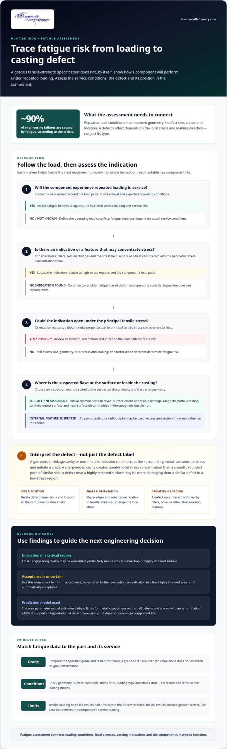
Ductile iron fatigue strength can be reduced when a casting defect raises local stress during repeated loading. A gas pore, shrinkage cavity, or non-metallic inclusion interrupts the surrounding metal, creating a discontinuity that can concentrate stress and initiate a crack. A defect near a highly stressed surface may be more damaging than a similar defect in a low-stress region.
Defect geometry matters as much as defect type. A sharp-edged cavity creates greater local stress concentration than a smooth, rounded pore of similar size. Orientation matters too: a discontinuity perpendicular to the principal tensile stress can open under load. For example, a pore at a fillet may interact with the geometric stress concentration there, raising fatigue risk.
The area parameter model estimates fatigue limits for metallic specimens containing small defects and cracks, with an error of about ±10 %. It considers the projected defect area rather than treating every indication as equivalent. This estimate helps explain how defect dimensions relate to fatigue performance, but specimen predictions should not be treated as a guaranteed component life.
Assessment connects each defect’s size and position with the component’s stress field and loading direction. Engineers can review radiographic or other inspection results alongside design features such as holes, fillets, and section changes. This helps distinguish defects in critical regions from those in less highly stressed areas, informing decisions about acceptance, redesign, or further evaluation.
Component durability and safety
Nearly 90% of engineering failures are caused by fatigue. Repeated loading can initiate a crack, then extend it until a component loses its ability to carry its designed load. Cars and trains can have durability expectations ranging from 108 to 1010 loading cycles. These demands make fatigue performance relevant to service life and safety.
Fatigue failure can develop without a single overload. A rotating shaft, for example, experiences repeated stress as it turns, and a crack may grow with each cycle. Changes in load, vibration, corrosion, or geometry can also affect performance in service. Engineers consider the load pattern, stress level, and expected operating conditions when assessing durability.
Inspection methods depend on the suspected defect and the part’s geometry. Visual examination can reveal surface cracks and visible damage. Magnetic-particle testing can help detect surface and near-surface discontinuities in ferromagnetic ductile iron. Ultrasonic testing or radiography may be used to examine internal features, with access and section thickness influencing the choice.
A useful safety assessment connects inspection findings to the component’s function. First, identify high-stress regions from the design and loading conditions. Next, choose an inspection method suited to the suspected flaw and accessible surfaces. Then assess each indication by its location, orientation, and effect on the load path. A crack near a critical connection, for example, may warrant closer engineering review than an indication in a lightly loaded area. Inspection informs durability decisions, but does not replace fatigue-based design or operating controls.
Ductile iron fatigue strength
Ductile iron fatigue strength describes resistance to crack initiation and growth under repeated stress. Material names alone do not provide a reliable basis for ranking ductile iron against grey cast iron, steel, or aluminium. For fatigue results to support a fair comparison, grade, geometry, surface condition, stress ratio, and loading type must be comparable.
Fatigue strength is assessed with cyclic tests that record stress and cycles to failure. One study tested EN-GJS-400-18 specimens from 10⁴ to 3·10⁶ loading cycles; area-parameter prediction equations apply at stress ratio R = −1. These test conditions matter: only a few ductile iron fatigue studies extend beyond 10⁷ cycles.
Microstructure affects crack initiation and propagation. In tested EN-GJS-400-18, graphite nodularity was approximately 80-85%, with about 50 nodules per mm², average nodule size near 50 μm, and ferritic content near 90%. Heat treatment changes the matrix and may alter strength, ductility, and fatigue response, so results apply to the tested condition.
Notches raise local stress, while component size can change the likelihood of critical defects and the stressed material volume. Loading type also matters: tensile and biaxial fatigue results can differ. For tensile loading, 82% of finite-life results fell within the 2× scatter band; biaxial results showed greater scatter. The practical takeaway is to use test data matching the part’s grade, geometry, stress state, and service loading.
There is no fixed ranking: ductile iron may compare differently with grey cast iron, steel, or aluminium depending on the grades and test conditions. A meaningful comparison requires like-for-like testing.
How does ductile iron fatigue strength vary by grade and tensile strength?
Higher tensile strength does not, by itself, mean higher fatigue strength. A grade specifies a set of mechanical properties, but fatigue response also depends on microstructure, defect population, surface condition, and loading. Comparisons are meaningful only when specimens have similar geometry, preparation, and test conditions.
A paper reports fatigue tests on three ductile iron grades across 106 up to 1010 cycles. This broad range matters because a grade’s performance over shorter tests may not describe behaviour under very long service histories. The available research facts do not provide a numerical ranking of the three grades, so tensile strength alone cannot establish which performed best.
For a practical comparison, match fatigue data to the specified grade and heat-treated condition, then review the stress ratio and loading mode. For example, a component under repeated tension needs evidence relevant to tensile cycling, not results from a different loading pattern. The fatigue limit also depends on the test’s cycle range.
Use tensile strength as one selection input, not as a substitute for fatigue data. Review the grade, microstructure, specimen condition, stress level, and cycles to failure together. If a component’s duty cycle extends beyond a test’s range, that test alone cannot establish expected fatigue performance. This helps distinguish a material specification from evidence of durability under repeated loading.
Ductile, Gray and Malleable Iron Castings
Ductile Iron has nodular graphite and combines high tensile strength with good ductility, making it suitable for medium to large castings. A pump housing or machinery support, for example, may need strength and resistance to cracking under service stresses. Select a grade based on the part’s loads, geometry, and operating conditions, not tensile strength alone.
Gray Iron contains flake-shaped graphite, which contributes to vibration damping and machinability. These characteristics can suit machine bases and housings where dimensional stability and reduced vibration matter. Graphite flakes also affect the material’s response to tension, so design requirements should determine whether Gray Iron suits the component’s function.
Malleable Iron is used for small castings that need good tensile strength and ductility. Its properties can suit compact fittings, brackets, and other small components subject to mechanical loads. Part size and required mechanical performance help determine whether Malleable Iron or Ductile Iron is a better fit for a specific design.
Compare the three materials against the finished part’s requirements. Start with load direction and magnitude, then consider geometry, section thickness, machining needs, and service environment. A vibration-sensitive machine base may favour Gray Iron, while a load-bearing component that needs ductility may point to Ductile Iron. Malleable Iron may suit a smaller casting that needs a balance of strength and ductility. Matching the material to these functional needs provides a sound basis for specifying an iron casting.
Bowmanville Foundry: Ductile Iron Castings
Bowmanville Foundry produces Ductile Iron Castings for manufacturers evaluating materials and casting requirements for cyclically loaded components. Its technical and sales engineers can discuss part geometry, specified grade, and service demands during an on-site visit. This connects design considerations with the casting specification.
Established in 1902, the foundry manufactures Ductile Iron, Gray Iron, and Malleable Iron castings. It also provides Post-Processing Services for projects requiring finishing operations. The foundry was the first in Canada to achieve ISO certification, in 1996.
For an initial project discussion, gather details such as the component’s function, drawings or CAD files, required material properties, and machining or finishing needs. These help frame a technical assessment of the design and production requirements. An on-site visit from a technical or sales engineer gives customers a direct way to discuss their application with the foundry.
The Free Casting Buyer’s Guide supports casting decisions and material selection. If a project needs finishing after casting, Post-Processing Services can be included in the discussion. The next step depends on the component’s geometry, grade requirements, and intended use.
For assistance with a casting project, contact Bowmanville Foundry.
Frequently Asked Questions
What is the fatigue strength of ductile iron in MPa?
No single fatigue-strength value in MPa applies to every ductile iron component. A useful value must identify the grade, material condition, stress ratio, loading mode, and cycle range. In design calculations, distinguish tensile strength from cyclic test results. Use data that represents the intended material condition and test basis, rather than treating one MPa value as universal.
What are the fatigue limits of common ductile iron grades such as 65-45-12 and 80-55-06?
The designations 65-45-12 and 80-55-06 do not state a universal fatigue limit. To compare them, use grade-specific fatigue data and confirm that the reported material condition and test basis match the design. An S-N curve may be more useful than a single fatigue-limit value when the component is designed for a defined finite service life.
How do casting quality, porosity, inclusions, and surface finish affect ductile iron fatigue strength?
For procurement and quality records, define how casting quality will be documented before production begins. Specify applicable inspection methods, which indications must be recorded, and how findings will be dispositioned. Record the surface condition at the stage relevant to the fatigue assessment, such as as-cast or machined. This creates a consistent basis for reviewing inspection results and supporting engineering decisions.
What are ductile iron S-N curves and fatigue data for different stress ratios?
An S-N curve relates cyclic stress to cycles endured before failure. Stress ratio, R, distinguishes fatigue data collected under different relationships between minimum and maximum stress. A ductile iron study used load-controlled tests at R-ratios of -8, -7, -3, -1, 0, 1/3, 0.5, and 0.75. Compare curves only after matching the ratio and test conditions to the intended application.
How should fatigue design safety factors be chosen for ductile iron components?
Choose the factor based on the governing design basis and a documented engineering assessment, not a universal value. Separate the fatigue check from the static-strength check, then state the load assumptions, selected fatigue data, and treatment of uncertainty. The required margin depends on design requirements and the consequences of failure. Keep the calculation traceable so later design or load changes can be assessed consistently.
What standards and test methods measure fatigue strength of ductile iron?
Fatigue strength is measured with cyclic tests that record stress and cycles to failure; results should match the grade, geometry, stress ratio, and loading mode. The area-parameter model estimates fatigue limits for specimens with small defects and cracks, with its prediction equations applying at R = −1.
