
A single millimetre of wall thickness or an overlooked fillet radius often marks the boundary between a high-performing component and a pile of expensive scrap. If you’ve ever dealt with unforeseen machining costs or structural failures from internal shrinkage, you know that the foundry floor is an unforgiving environment for poor geometry. This iron casting design guide helps you navigate these technical complexities, bridging the gap between a theoretical CAD model and a dependable, manufacturable part. It’s a common challenge for engineers who need to balance structural integrity with tight production budgets and the precision required in a modern, automated foundry.
We’ll show you how to select the right iron grades, optimize section transitions to prevent defects, and use a practical checklist to ensure your designs are at the centre of a cost-effective production cycle. By following these established principles, you can reduce production costs and ensure your industrial components meet the highest standards of reliability. We’ll provide the technical certainty you need to make informed decisions that improve both your bottom line and your product performance in a competitive 2026 market.
Key Takeaways
- Learn to select the optimal iron grade, such as gray, ductile, or malleable iron, to match your specific mechanical requirements and vibration damping needs.
- Use this iron casting design guide to maintain uniform wall thickness and optimize geometry, which helps prevent cooling stresses and internal defects.
- Master the principles of metal solidification to identify potential heat reservoirs and design out the voids caused by volumetric contraction.
- Factor in precise machining allowances and sand casting tolerances early to ensure your final components meet exact dimensional specifications after finishing.
- Realize the benefits of early collaboration with an experienced Canadian foundry to reduce lead times and avoid the high costs of late-stage redesigns.
Selecting the Right Iron Grade for Your Design
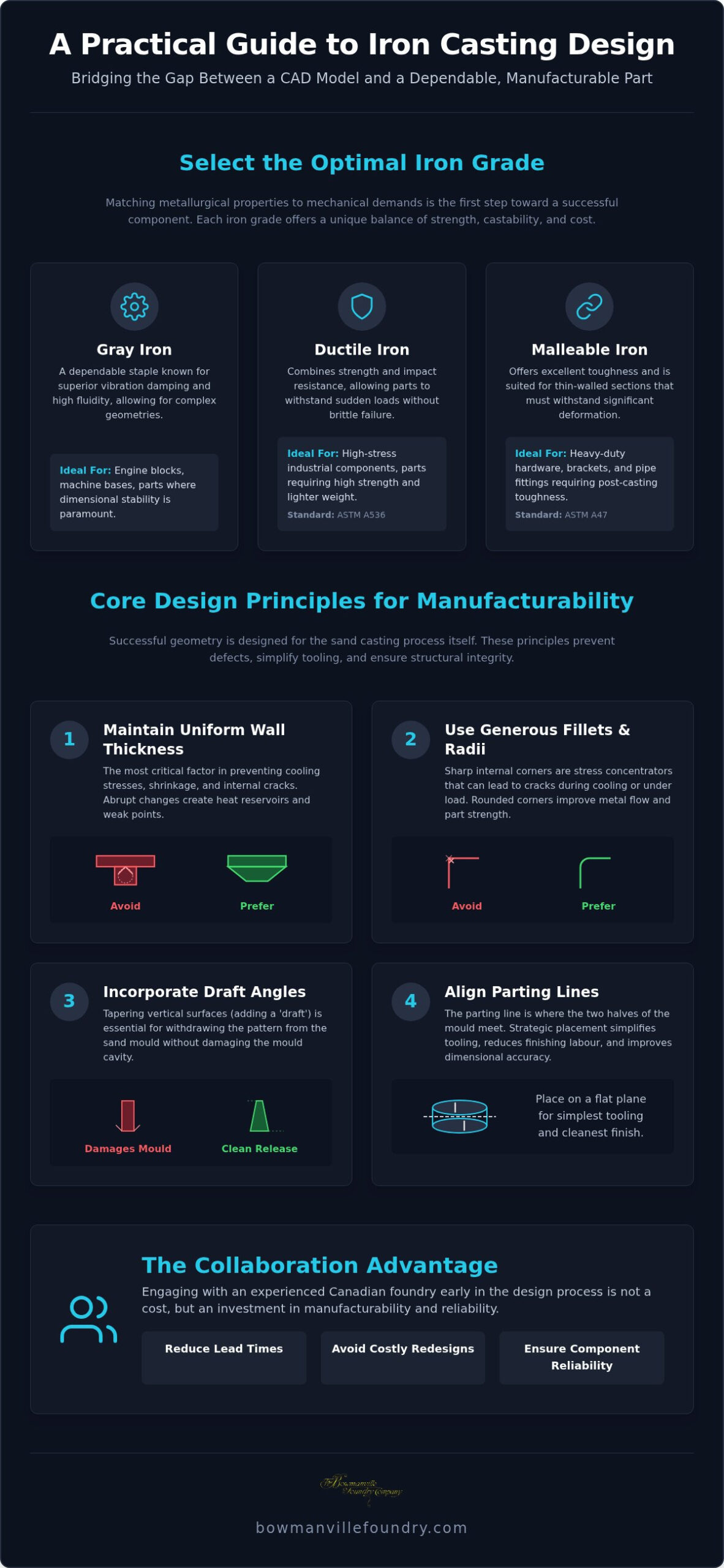
Successful iron casting design begins with a precise match between the metallurgical properties of the metal and the mechanical demands of the application. It isn’t enough to design for shape alone; you must account for how the metal behaves during solidification and its final performance under load. In this iron casting design guide, we emphasize that selecting the right grade is a balance of strength, castability, and cost. Gray iron remains a dependable staple for complex geometries and applications requiring superior vibration damping. It’s the ideal choice for engine blocks or machine bases where tensile stress is relatively low but dimensional stability is paramount. For a broader Cast Iron Overview, engineers can review the historical development of these alloys to understand why specific microstructures, like the flake graphite in gray iron, provide these unique benefits.
Ductile iron is the preferred choice for high-stress industrial components. It’s characterized by nodular graphite, which provides a combination of strength and impact resistance that gray iron lacks. When your design demands the ability to withstand sudden loads without brittle failure, ductile iron is the standard. Malleable iron is a grade often overlooked by general foundries but mastered over 120 years at Bowmanville Foundry. It offers excellent toughness and is particularly suited for thin-walled sections. Its unique heat-treatment process transforms brittle white iron into a material that can withstand significant deformation. This makes it ideal for heavy-duty hardware, brackets, and pipe fittings that require post-casting toughness.
Comparing Mechanical Properties
Choosing between these grades requires a careful evaluation of tensile strength versus ductility. While ductile iron provides higher absolute strength, the “castability” of the metal is equally critical. This refers to the ability of the molten iron to flow into intricate mould cavities without creating internal defects. Gray iron’s high fluidity allows for thinner ribs and more complex cooling fins than some ductile grades. Material choice also directly impacts the final weight of the component. By selecting a higher-strength grade like ductile iron, you can often reduce section thickness. This leads to a lighter part that maintains structural integrity while lowering shipping and handling costs.
Selecting ASTM Standards
To ensure consistency and quality control, your design specifications must align with recognized industry standards. For Canadian projects involving malleable iron, refer to ASTM A47. This standard defines the required tensile strength and yield point for various malleable grades, ensuring the foundry delivers a product that meets your engineering calculations. When your project requires ductile iron, utilize ASTM A536 for grade selection. This standard is essential for verifying that the nodular graphite structure has been correctly formed. Specifying these ASTM grades in your design notes provides a clear framework for quality testing and reduces the risk of material-related failures. This technical precision is a core component of any professional iron casting design guide.
Core Design Principles: Geometry and Manufacturability
Geometry is the physical blueprint of manufacturability. While the previous section focused on metallurgy, the physical form of your component determines how effectively molten iron fills the mould cavity and solidifies without defect. This iron casting design guide emphasizes that successful geometry isn’t just about the final part’s function; it’s about designing for the sand casting process itself. Practical engineering requires a shift in perspective, where the designer visualizes the liquid metal’s path and the eventual removal of the pattern from the sand. To achieve this, engineers should follow a logical progression of design steps:
- Maintain uniform wall thickness: This is the most critical factor in preventing cooling stresses and internal cracks.
- Incorporate adequate draft angles: Vertical surfaces must be tapered to allow the pattern to be withdrawn without damaging the sand mould.
- Use generous fillets and radii: Sharp corners are stress concentrators and should be eliminated to ensure structural integrity.
- Align parting lines: Strategic placement of the parting line simplifies tooling and reduces the labour required for finishing.
Wall Thickness Guidelines
Uniformity is the primary goal for any iron casting. When a design features abrupt changes in section thickness, the thinner areas cool and solidify faster than the heavier sections. This temperature differential creates “hot spots” that lead to internal shrinkage or warping. If your design requires varying thicknesses, use gradual tapers to transition between sections. According to the Iron Castings Engineering Handbook, a 1:4 ratio for tapers is often recommended to maintain a steady cooling rate. Minimum wall thickness also varies by iron grade; gray iron can often be cast in thinner sections than ductile iron due to its superior fluidity. You can often resolve these geometric challenges by consulting with an engineering-focused foundry during the early CAD stages.
Draft Angles and Fillets
Draft angles are essential for the physical production of the mould. Without a slight taper, the friction between the pattern and the sand will cause the mould to tear during removal. For most industrial iron castings, a draft angle of 1.5 to 3 degrees is standard. While smaller angles are possible for deep pockets, they increase the risk of mould breakage and higher scrap rates. Fillets and radii serve a dual purpose: they improve the flow of molten iron and distribute mechanical stress more evenly across the part. Sharp internal corners are notorious for causing casting cracks during the cooling phase. By calculating fillet radii that are proportional to the wall thickness, you ensure the metal flows smoothly into every corner of the cavity, resulting in a denser, more reliable component. This methodical approach to geometry is what separates a theoretical model from a high-quality industrial casting.
Managing Metal Solidification and Shrinkage
Iron transforms from a liquid to a solid state through a process of volumetric contraction. As the molten metal cools within the mould, it occupies less space, which can lead to internal voids or surface depressions if the design doesn’t account for this physical reality. An effective iron casting design guide must prioritize the management of these thermal gradients. When certain areas of a casting remain liquid longer than others, they act as heat reservoirs. Without a continuous supply of molten metal to “feed” these areas, the resulting vacuum creates shrinkage cavities that compromise the part’s structural integrity. Achieving a sound casting requires a deep understanding of Casting Design for Foundry Practice, where the geometry is engineered to encourage solidification to move progressively from the thinnest sections toward the heaviest ones.
This principle is known as directional solidification. By ensuring the metal freezes in a controlled sequence, the foundry can position risers; external reservoirs of molten iron; to feed the shrinking sections until the entire part is solid. Successfully managing this process isn’t a solo task for the designer. It requires close collaboration with your foundry partner to determine the optimal placement of gates and risers. At Bowmanville Foundry, we’ve spent over 120 years refining these techniques to ensure that even the most complex industrial components are free from internal defects.
Ribs and Bosses for Structural Integrity
Engineers often face the challenge of increasing a component’s stiffness without adding excessive mass that complicates the cooling process. Ribs are an excellent solution, providing structural reinforcement while maintaining a relatively thin cross-section that cools quickly. However, the spacing of these ribs is critical. If ribs are placed too closely together, the sand between them can become overheated, creating a “hot spot” that slows cooling and leads to shrinkage. Similarly, bosses intended for mounting or machining should be kept as small as possible. A massive boss on a thin wall creates an isolated heavy section that’s difficult to feed, often resulting in a porous centre that fails during final machining.
Preventing Internal Defects
The most effective way to eliminate shrinkage cavities is to design for consistent cross-sections that allow for a steady, predictable cooling rate. When isolated heavy masses are unavoidable, foundries use “chills”; metal inserts placed in the sand mould; to accelerate cooling in those specific areas. This helps equalize the temperature across the part, but it’s a technical workaround rather than a primary design strategy. Designers should review their CAD models for any “islands” of thick metal that are cut off from the main feeding path by thinner sections. If the liquid metal cannot reach a heavy section because the surrounding walls have already solidified, an internal void is almost certain to form. This methodical focus on solidification is a cornerstone of a professional iron casting design guide and is essential for producing high-reliability industrial parts.
Sand casting is an inherently variable process. While modern automation has improved consistency, an iron casting design guide must acknowledge that “as-cast” dimensions will always have a tolerance range. In Canada, these tolerances are typically governed by industry standards that account for pattern wear, sand expansion, and metal contraction. If your component requires high-precision fits, you must design with the intent to machine specific surfaces. This means providing an adequate machine finish allowance; usually between 2 mm and 4 mm; to ensure that the machinist can remove the hard casting skin and reach the stable metal underneath without excessive tool wear.
Machining Allowances and Datum Points
A common error in industrial design is failing to provide enough material for secondary operations. If the allowance is too thin, the cutting tool may skip over the surface or dull prematurely against the abrasive casting skin. Establishing clear datum points is equally vital. These are the fixed reference surfaces that both the foundry and the machinist use to measure the part. These points should be located on the same side of the parting line whenever possible to minimize the impact of mould shift. If you’re planning for extensive post-processing, it’s best to consult with our engineering team to ensure your datum points are positioned for maximum stability during the machining cycle.
Surface Finish and Coating
Not every surface requires a mirror finish. Designing for “as-cast” surfaces wherever possible reduces production time and costs. However, when functional requirements demand a specific texture, you must specify the required Ra value in your drawings. Surface coatings also play a significant role in the final tolerance stack-up. For example, hot-dip galvanizing, a frequent requirement for Canadian industrial hardware, adds a measurable layer of zinc to the surface. If your tolerances are too tight, the part may no longer fit into its assembly after coating. You must also identify where parting line flash is acceptable. While foundries grind these areas, specifying the required level of smoothness prevents unnecessary labour costs on non-critical surfaces.
Finally, consider the metallurgical impact of post-processing. Grades like malleable iron require a rigorous annealing cycle that can cause slight dimensional growth or contraction. By accounting for these shifts during the initial design phase, you ensure the final product remains within specification after all heat treating and finishing is complete. This holistic view of the production lifecycle is what ensures a successful, cost-effective industrial component. Using this iron casting design guide as a framework allows you to anticipate these requirements before the first mould is even poured.
Optimising Production with Professional Foundry Collaboration
The transition from a digital CAD model to a physical iron component is rarely a straight line. While this iron casting design guide provides the foundational rules for geometry and metallurgy, the most successful projects are those where the foundry is involved before the design is finalized. Early collaboration allows engineers to identify potential casting failures, such as trapped gases or cooling imbalances, before a single dollar is spent on tooling. Leveraging the institutional knowledge of a Canadian foundry with over 120 years of experience ensures that your component is optimized for the specific sand casting equipment used on the floor. This proactive approach significantly reduces lead times and prevents the costly, time-consuming redesigns that often plague late-stage procurement.
The Design Review Process
Modern foundry collaboration relies on thorough digital design reviews. By sharing your 3D models early, you gain access to expert feedback on manufacturability that automated quoting tools simply cannot provide. We evaluate your volume requirements to determine the most efficient moulding method, whether that involves high-speed automated lines or specialized manual processes. We also verify that your iron grade selection remains appropriate for the intended operating environment; whether it’s the high-impact needs of mining or the vibration-damping requirements of industrial machinery. Pattern development is another critical phase where collaboration pays off. The pattern is the heart of the production timeline, and subtle adjustments made during the review process can simplify tooling and lower per-part costs.
Resources for Casting Buyers
For procurement teams and lead engineers, the complexity of industrial casting requires a structured approach to decision-making. We recommend that you download the Free Casting Buyer’s Guide to access a detailed checklist for your next project. This resource acts as a companion to our iron casting design guide, offering practical advice on managing supplier relationships and verifying quality standards. If you’re currently comparing malleable versus ductile iron for a specific application, our technical team can provide a side-by-side analysis of mechanical properties to ensure you select the most durable material. Organizing a technical consultation is the most effective way to review custom engineered iron components and ensure your designs are ready for the rigours of 2026 manufacturing. We value precision and transparency, positioning our foundry as a partner in your long-term success rather than just a supplier.
Engineering Success through Technical Precision
Adhering to the principles outlined in this iron casting design guide ensures that your industrial components are built for both performance and manufacturability. By selecting the correct iron grade and optimizing geometry for the sand casting process, you mitigate the risks of internal shrinkage and unforeseen machining costs. We’ve established that managing thermal gradients and factoring in post-processing requirements early are essential steps for any high-stakes project. These technical decisions form the foundation of a reliable production cycle.
Bowmanville Foundry has delivered Canadian manufacturing excellence since 1902, acting as a specialist in custom engineered iron components. Our facility provides comprehensive post-processing and finishing services to ensure your parts arrive ready for assembly. To gain deeper insights into the procurement process and technical specifications, Download Your Free Iron Casting Buyer’s Guide. We’re ready to help you turn these design principles into durable, physical solutions that stand the test of time.
Frequently Asked Questions
What is the minimum wall thickness for a gray iron casting?
Gray iron typically requires a minimum wall thickness of 3 mm to 6 mm for small to medium castings. For larger or more complex industrial components, this minimum increases to ensure the molten metal doesn’t solidify prematurely. Maintaining these minimums prevents “cold shuts” and ensures the metal fills the mould cavity completely. It’s a fundamental rule that ensures the fluidity of the iron matches the complexity of your design.
How much draft angle should I include in my iron casting design?
You should include a draft angle of 1.5 to 3 degrees on all vertical surfaces. This slight taper allows the pattern to be withdrawn from the sand mould without damaging the cavity walls. While internal pockets may require a slightly larger angle to prevent sticking, following these standards in your iron casting design guide reduces scrap rates and improves production efficiency. Proper draft is essential for maintaining the integrity of the sand mould.
What is the difference between as-cast and machined tolerances?
As-cast tolerances reflect the inherent variability of the sand casting process, while machined tolerances provide the precision required for functional fits. Sand casting typically achieves tolerances within a few millimetres. Machining removes the outer casting skin to reach exact dimensions, often down to microns. Designers must provide adequate finish allowances, usually 2 mm to 4 mm, to account for this transition and ensure the final part meets specifications.
Can I cast internal threads directly into an iron component?
No, you cannot effectively cast small internal threads directly into iron components using standard sand casting. The sand cores required for threads are too fragile to withstand the heat and pressure of molten iron. Instead, you should design the part with a solid boss that can be drilled and tapped during post-processing. This ensures thread integrity and structural reliability while preventing the crumbling of sand into the molten metal.
How do I choose between malleable and ductile iron for my design?
Choose malleable iron for thin-walled sections that require high toughness and impact resistance. It’s particularly effective for heavy-duty hardware and brackets where deformation without failure is critical. Ductile iron is better suited for larger, high-stress components where absolute tensile strength and yield strength are the priorities. Consulting with a foundry specialist helps determine which grade aligns best with your part’s geometry and mechanical requirements.
What are the most common causes of iron casting defects?
Most defects stem from improper solidification management or gas entrapment. Shrinkage cavities occur when heavy sections aren’t properly fed with molten metal, while “blows” happen when moisture or gas can’t escape the mould through the sand. Poorly planned parting lines can also lead to mould shift, resulting in dimensional inaccuracies. Using a comprehensive iron casting design guide helps identify these risks during the CAD phase before production begins.
How does heat treating affect the design of my iron component?
Heat treating can cause slight dimensional growth or contraction as the iron’s microstructure changes. For example, the annealing process required for malleable iron often results in predictable expansion. You must account for these shifts in your initial CAD models to ensure the final part remains within tolerance. Heat treating also relieves internal stresses, which improves the part’s stability and prevents warping during subsequent high-precision machining operations.
Why is uniform wall thickness so critical in iron casting?
Uniform wall thickness is critical because it ensures a steady and predictable cooling rate across the entire part. When sections vary significantly in thickness, the thinner areas solidify faster, creating internal stresses and potential shrinkage voids in the heavier sections. This principle is a cornerstone of professional engineering, as it directly prevents warping and structural failure. Consistent sections allow the metal to solidify progressively toward the risers.
