
Cast iron castability depends on geometry as much as material choice: uniform walls, gradual thickness changes, and simplified internal features help a component fill and solidify more predictably. For ductile iron, a recommended minimum wall thickness is 4-5 mm, though the application and casting design affect what is suitable. A sound approach to cast iron component design for manufacturability considers how the part will be moulded, cooled, and machined before its geometry is finalized.
It’s easy to focus first on strength, wear resistance, or required dimensions. Yet a part can meet its drawing requirements and still be difficult to cast if it has isolated heavy sections, sharp internal corners, or complex cores.
This article explains how to compare gray iron, ductile iron, and Malleable Iron for an application; assess wall thickness and transitions; and review drawings, tolerances, machining allowances, and mould features. It also covers how fillets, core design, and casting orientation can help reduce hot spots and support reliable production. These checks connect performance requirements to practical casting geometry.
Key Takeaways
- Match gray iron, Ductile Iron, or Malleable Iron to the component’s loading, operating conditions, and functional requirements.
- Assess wall thickness against the casting material and process, and avoid designing thin sections that may be difficult to fill consistently.
- Review datums, functional surfaces, tolerances, and machining allowances together before tooling or pattern work begins.
- Use gradual wall transitions and core out heavy sections where practical to reduce isolated hot spots and shrinkage risk.
- Simplify internal features, add suitable fillets, and consider mould opening direction to support castability and downstream machining.
Recommended wall thickness by casting material and process
Wall thickness depends on the iron grade, component geometry, and casting process. Ductile iron wall thickness should be chosen with the component geometry and casting process in mind. Truck components have separate reference values: 8-10 mm for gray iron and 6-8 mm for ductile iron. These values are starting points, not universal dimensions; flow paths, section length, and function also shape the design.
How do draft angles, parting lines, cores, and machining allowances affect cast iron component design? Draft helps release the pattern from a sand mould, while the parting line defines where the mould separates. Cores form internal cavities, and machining allowances reserve material for finished surfaces and dimensional requirements.
For cast surfaces, draft depends on process and feature depth. General guidance gives 1-3° for external surfaces and 2-5° for internal surfaces, with more draft on internal features. Deeper features need larger angles. Draft requirements vary by casting process; sand casting needs draft for pattern removal, while investment casting may need little or none. These figures are design references, not interchangeable requirements for every geometry.
Minimum wall thickness also varies across casting materials and processes. The listed reference for aluminum castings is 2-3 mm, while resin sand casting is listed at 3-4 mm. Those figures should not be transferred directly to cast iron. The iron grade, mould design, and component shape affect whether a section fills and solidifies as intended.
Parting-line placement affects mould complexity and the location of mould joints on the casting. A core creates hollow sections but adds another feature to the mould design. For surfaces that will be machined, allow stock for material removal: typical allowances are 2-4 mm per side on external diameters and 2-4 mm for internal bores. Identify these surfaces on the drawing so as-cast dimensions and finished dimensions are not confused.
Choose a process to suit the part’s size, detail, and production volume. Sand casting suits larger parts and low to medium production volumes. Investment casting suits fine detail and near-net shapes. Shell moulding is also used for cast iron components. Compare the geometry and finish requirements with the process before finalizing wall sections. A process suited to large, simple parts may not suit intricate details.
Design improvements can involve alloy formulations, casting methods, and post-casting treatments to address properties such as strength, wear resistance, or machinability. These choices complement, rather than replace, sound wall design. Review the material, process, cores, draft, and machining stock together so the production requirements are reflected in the component drawing.
Selecting castable materials, including gray iron
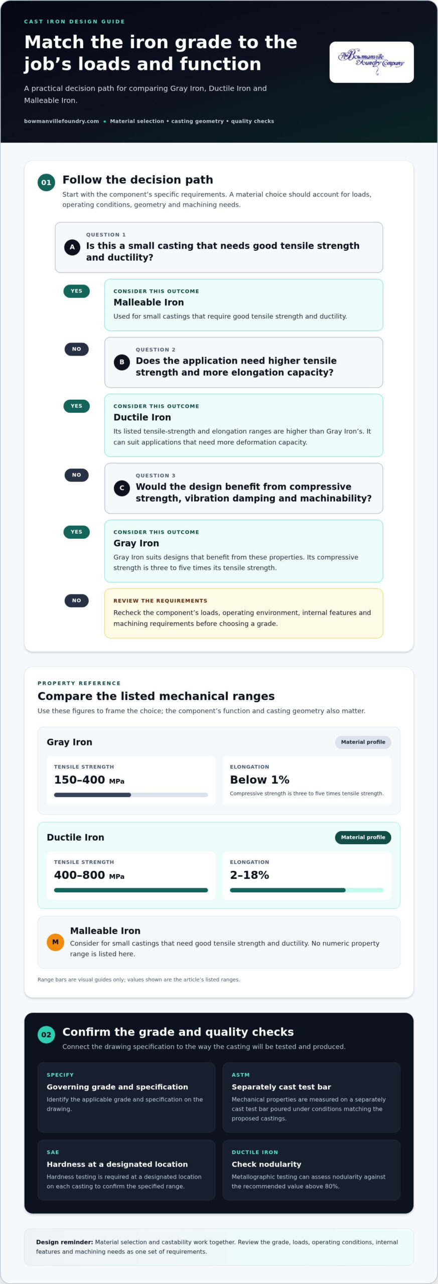
Material selection starts with the component’s loads, operating environment, and required properties. Gray cast iron has a listed tensile-strength range of 150-400 MPa and elongation below 1%. Ductile cast iron is listed at 400-800 MPa tensile strength, with elongation of 2-18%. These ranges help frame the choice, but the component’s function and casting geometry also matter.
Gray iron suits designs that benefit from its compressive strength, vibration damping, and machinability. Its compressive strength is three to five times its tensile strength. Ductile Iron offers greater tensile strength and elongation in the listed ranges, making it suitable for applications that need more deformation capacity. Malleable Iron is used for small castings requiring good tensile strength and ductility. Compare these properties with the actual loads, internal features, and machining requirements.
Which Canadian and international standards apply to cast iron grades, testing, and quality assurance? Identify the governing grade and specification for the application on the drawing. ASTM specifications use mechanical properties measured on a separately cast test bar poured under conditions matching the proposed castings. SAE specifications require hardness testing at a designated location on each casting to confirm the specified range.
What tolerances and surface finishes are achievable for sand-cast iron components? A typical sand-casting tolerance is ±0.030 inches (±0.75 mm), and a typical surface finish is 200-400 μin Ra. Tighter dimensional requirements generally belong on machined features, where the drawing can define the functional surfaces and their tolerances.
What are the main failure risks and inspection methods for cast iron components? Long-term loads, vibration, and elevated temperatures make grade selection and casting-process control important; isolated heavy sections can also develop shrinkage porosity. Hardness testing checks a specified property, while metallographic testing can assess ductile iron nodularity against the recommended value above 80%.
Quality control starts with suitable material preparation and continues through melting, pouring, cooling, shakeout, and machining. Each stage can affect casting quality, so connect the material specification to the production process. For example, identify functional surfaces on a component with tight machined tolerances, while ensuring its cast sections suit the selected grade and geometry. Reviewing these requirements together supports consistent production.
Make a sound selection by weighing application conditions, manufacturing requirements, machining needs, and production stability, not castability alone. Gray and ductile iron properties provide useful comparison points, but specify mechanical properties for the component’s intended service. Clear grade requirements and defined inspection criteria give production and quality teams a shared basis for evaluating each casting.
Drawing and specification review
A drawing review connects part geometry, material requirements, casting feasibility, and machining needs before production decisions are fixed. It helps the design team define what the casting must achieve and how the foundry will measure it.
Design Reviews Before Tooling
A design review examines the drawing and specification before pattern or tooling is made. Engineers can assess whether the dimensions, material properties, and functional surfaces suit the component’s intended use. For example, a housing drawing should distinguish surfaces that require machining from those that remain as-cast. Reviewing these details early helps prevent design changes from disrupting tooling, production planning, and sample approval.
Start with the component’s required strength, service conditions, and material grade. Then compare its geometry with casting and machining requirements. Identify critical dimensions, tolerances, and datums so inspection and machining teams use consistent reference points. Clearly specify functional surfaces. Otherwise, a dimension may be treated as critical even when it does not affect assembly or performance.
Drawings should show how the part will be located for measurement and post-casting machining. Flat datum surfaces can provide stable fixturing, while defined datums help locate each casting consistently in the machine shop. Add machining allowance to precision surfaces and state which dimensions apply before or after machining. This distinction prevents confusion between the casting’s form and the finished component.
Apply tight tolerances only where function requires them. For example, the design guidance gives ±0.002 inches for bearing seats and ±0.005 inches for mounting holes when those tolerances are functionally critical. As-cast surfaces generally do not need the same precision as machined interfaces. A clear specification lets manufacturing teams focus control on features that influence fit, alignment, or operation.
DFM Reviews for Manufacturing Fit
A design-for-manufacturability review evaluates whether the specified part can be cast and finished efficiently. It matters because unnecessary precision, complex geometry, or unclear requirements can lead to avoidable pattern revisions, machining, and production rework. The review aligns the drawing with the foundry process before the requirements reach the shop floor.
For a cast iron component design for manufacturability review, assess CAD files alongside the drawing. Production quote files should be in STEP or IGES format, watertight, and free of geometry errors. Confirm that the model and drawing agree on dimensions, features, and material specification. Clear, matching files reduce interpretation problems across design, tooling, and production teams.
Assess cooling and section geometry together when reviewing casting feasibility. A design that concentrates material may cool differently from adjacent sections, while machining requirements can affect how the casting is supported and located. Resolving these interactions before tooling helps teams set practical inspection points, tie specifications to function, and develop a production design that meets the component’s requirements.
Uniform wall thickness and hot-spot prevention
Wall layout affects how a casting cools and solidifies. Review heavy junctions and transitions as part of the component’s overall geometry.
Consistent Wall Thickness
Consistent wall thickness means keeping adjoining sections as even as the component’s function permits. This supports more uniform cooling and helps avoid isolated masses within the casting. A design-review reference is to keep thickness within 20% where practical. Treat this as a review target, not a reason to reduce material needed for a functional feature.
Assess each boss, rib, and junction in relation to its surrounding walls. If a mounting boss needs added material, consider how its shape joins the main body rather than leaving a sudden step. The recommended wall-thickness transition taper is at least 1:4. Applying a gradual transition helps the geometry move between sections without concentrating excess material at the junction.
Assess the part’s weight and load path together. Removing material from a load-bearing feature can compromise its function, while unnecessary mass can create uneven section geometry. Mark areas that need support, then review adjacent sections for abrupt changes. This makes the drawing review specific to the component’s application and structural requirements.
Shrinkage Porosity and Hot Spots
A hot spot is a region of concentrated material that cools later than the surrounding sections. Uneven solidification can contribute to shrinkage porosity. Pay particular attention to junctions where several walls meet, as they may create a heavier local section than the individual walls suggest.
Trace these intersections through the design and determine whether each needs its full mass. For example, a thick boss connected to a thinner housing wall may create a localized heavy region. Consider redistributing material or reshaping the junction for a more gradual transition. This addresses the geometry associated with hot spots while preserving required features.
Assess porosity in the context of the whole casting, including the relationship between adjoining sections. Mark concentrated junctions on the drawing for focused engineering review. The aim is to avoid unnecessary heavy regions and support consistent solidification across the part.
Core-Outs and Wall-Thickness Guidelines
A core-out creates a hollow region in a section that would otherwise contain unnecessary solid mass. It can reduce concentrated material while preserving the external form required for the component’s function. For example, review a thick housing region for a core if its internal volume is not needed for strength or mounting.
Assess the remaining walls and transitions around the cored area. Avoid creating new heavy junctions where the core ends or a boss meets the outer wall. Consider how the internal feature will be supported and accessed during production. Its shape should serve the component’s function, not add complexity without a purpose.
Show the core boundary and surrounding geometry clearly in the drawing. This gives design and production teams a shared reference for reviewing the section. If a core-out cannot preserve the required function, adjust the surrounding shape to avoid unnecessary solid mass while retaining the intended load path.
Cast iron castability and design complexity
Castability depends on how part geometry interacts with mould filling, solidification, and finishing. Key design-for-manufacturability principles include simplifying features, aligning them with the mould opening, and matching geometry to the material’s mechanical requirements.
Balancing Castability with Part Complexity
Castability is the ability to produce a sound casting from a design using the selected process. It matters because each added feature can affect mould construction, metal flow, or cleaning. For example, a deep internal passage may require a core, while an external rib may be formed directly by the mould.
Geometry also affects solidification rate and final strength. Long, thin sections and sudden changes in cross-section can complicate metal flow, so review those transitions against the component’s function. Aligning features with the mould-opening direction can simplify the pattern and mould arrangement.
Internal corners deserve particular attention. Sharp intersections concentrate stress and can be prone to hot tearing; fillets at internal corners support castability and fatigue life. A general design reference sets fillet radius at one-quarter to one-half of wall thickness. For walls 6-12 mm thick, the listed range is 4-6 mm; for walls 12-25 mm thick, it is 6-10 mm.
More geometry is not always more useful. Every core adds design and production considerations, including whether internal features can be supported and cleaned reliably. Check whether a passage, recess, or undercut serves a functional purpose. Undercuts can require complex side cores, so simplify them where practical or retain them only when the part’s function justifies the added mould complexity.
Applying Cast-Iron DFM Principles
Cast-iron design for manufacturability accounts for casting-process constraints early while preserving required performance. Design choices affect mould features, cooling behaviour, machining access, and the mechanical characteristics of the finished component.
Use a drawing review to compare the prototype geometry with its intended application. Check that the mould-opening direction suits the major features, internal details have a clear purpose, and sharp corners have suitable radii. Symmetrical geometry can help reduce warping and distortion, while gradual section changes support metal flow.
Choose material to suit service demands, rather than treating the drawing as geometry alone. A component requiring wear resistance or high strength needs a grade suited to those mechanical demands. Part size, complexity, and casting process also affect which design details are practical. Clearly identify critical interfaces so downstream machining can achieve the required fit.
A useful engineering review asks whether each complex feature improves function enough to justify its mould requirements. For example, replacing an unnecessary undercut with a simpler external contour may avoid a side core. Review fillets, core features, symmetry, and mould orientation together. These characteristics determine whether design intent translates into a practical casting.
For a technical discussion of a cast iron design, share your component requirements.
Bowmanville Foundry: Malleable Iron Castings
Bowmanville Foundry manufactures Malleable Iron Castings, Gray Iron Castings, and Ductile Iron Castings for industrial components. Consider its castings when selecting an iron grade for a component’s operating demands or coordinating casting requirements with finishing needs. The foundry also provides Post-Processing Services for secondary work after casting.
For a design discussion, prepare the component drawing, material requirements, and critical finished-part dimensions. These details focus the conversation on your application and production requirements.
To discuss your casting requirements or visit the website, contact Bowmanville Foundry.
Move Your Casting Design Toward Production
Bring the design intent and manufacturing requirements into the same discussion. A cast iron component design for manufacturability review can help translate the drawing into a component that reflects its intended function and material requirements. Prepare the current drawing, grade specification, and any critical interface requirements to focus the discussion on the decisions that shape the part.
Bowmanville Foundry offers Malleable Iron Castings and Ductile Iron Castings for different material requirements, as well as Post-Processing Services for finishing needs. Share how the component will be used and which surfaces must meet assembly requirements to give the technical discussion a practical starting point.
To discuss your casting design and next steps, contact Bowmanville Foundry. A clear design conversation can help move your project forward with confidence.
Frequently Asked Questions
How do grey iron and ductile iron differ in strength, machinability, and design requirements?
Gray iron generally suits designs where vibration damping and machinability are valued, while ductile iron is selected when greater tensile strength and elongation are needed. For example, a machine base designed to damp vibration presents different priorities from a bracket exposed to tensile loading. Compare the component’s loads, machined features, and operating conditions with the grade’s specified mechanical properties before finalizing the design.
What minimum wall thickness and section thickness rules apply to cast iron parts?
There is no single minimum that applies to every cast iron part; geometry, grade, and process all influence the design. The recommended minimum for ductile iron is 4-5 mm. For truck components, the references are 8-10 mm for grey iron and 6-8 mm for ductile iron. Treat these as design guidance, then review section length and function rather than applying one figure to every feature.
How should ribs, bosses, fillets, and transitions be designed to prevent casting defects?
Design ribs and bosses to support the component’s function without creating abrupt concentrations of material. Blend them into adjoining walls with gradual transitions, and use radii at internal corners instead of sharp intersections. A general fillet reference is one-quarter to one-half of wall thickness. For example, taper a rib into a housing wall rather than ending it in a thick, abrupt junction.
How can designers reduce shrinkage, porosity, hot spots, and residual stress in iron castings?
Reduce concentrated mass and abrupt section changes, because isolated heavy regions cool later and can develop shrinkage porosity. Core out solid sections where the part’s function allows, and keep the geometry as symmetrical as practical to help limit warping. Casting-process control also matters. Inspection can include hardness testing at a specified location; metallographic testing can assess ductile iron nodularity when required.
How do casting process options affect design, lead time, and cost for cast iron parts?
Sand casting suits larger parts and low to medium production volumes, while investment casting suits fine detail and near-net shapes. Process choice affects mould and pattern requirements, core use, machining needs, and production planning. These factors influence project resources, and no single cost applies to every design. Typical lead times are four to eight weeks, depending on current business conditions; geometry and tooling requirements also shape the schedule.
