
What determines whether a sand-cast part has the cavities and finished surfaces its application requires? Designing for the sand casting process starts with shaping the mould around a pattern; a core forms an intentional internal cavity, while the gating system directs molten metal into the mould. The geometry must also allow the pattern to release cleanly.
It’s natural to focus first on the cavity, but its shape is only one part of the design. Draft, wall thickness, shrinkage and metal flow all affect how a casting forms. Machining and other post-casting processes also determine which surfaces need stock or specific dimensions.
This guide explains how patterns and cores form casting cavities, and how draft and gating help shape and fill them. It also covers thick sections, shrinkage, intended use and post-processing, giving you a practical basis for discussing manufacturability and iron casting requirements with a foundry.
Key Takeaways
- Choose draft to suit the casting’s geometry so the pattern can release cleanly from the mould.
- Use rounded transitions and plan metal flow to support complete filling and reduce stress concentrations.
- Review thick sections and solidification together to help limit shrinkage-related defects.
- Connect material choice and finishing requirements to the part’s intended use, then explore the foundry’s technical support and post-processing services.
Draft angle for casting release
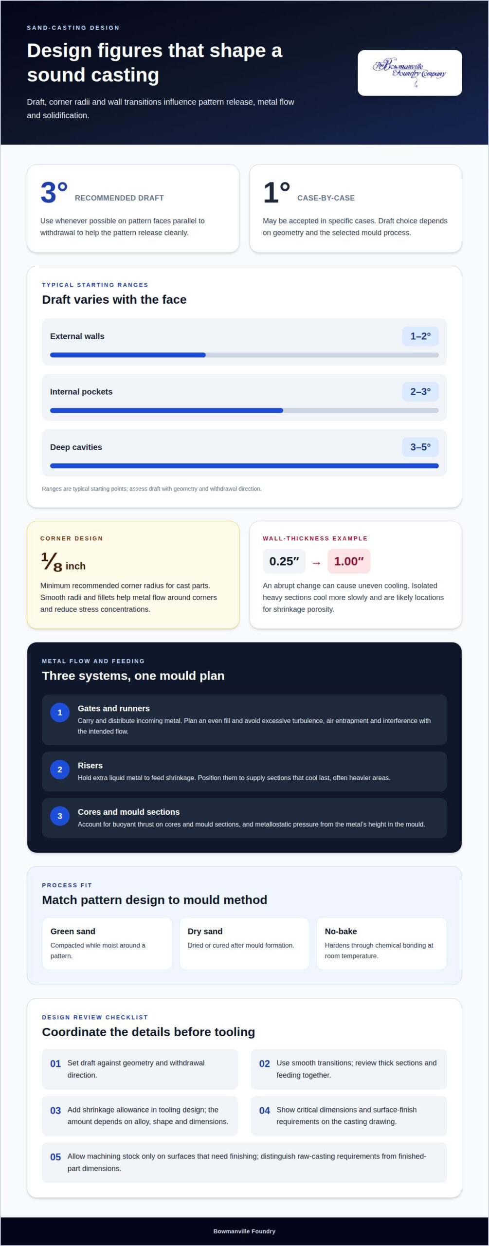
When designing for the sand casting process, include draft on pattern faces parallel to withdrawal. A three-degree draft is recommended whenever possible; one degree may be accepted case by case. Typical starting ranges are 1-2° on external walls, 2-3° in internal pockets and 3-5° in deep cavities. These tapers help release the pattern without damaging the cavity.
Green sand is compacted while moist around a pattern. Dry-sand moulds are dried or cured, while no-bake moulds harden through chemical bonding at room temperature. Each method supports the mould differently, so pattern design and draft must suit the selected process.
Canadian foundries must meet applicable workplace-safety and environmental requirements. The relevant controls depend on the province and the facility’s processes.
Tooling requirements and minimum order quantities depend on pattern complexity, material and production setup. Batch size and manufacturing requirements also shape the production plan.
For effective design in the sand casting process, assess draft together with wall thickness, withdrawal direction and fillet radii. Smooth transitions can help metal flow, while changes in thickness affect solidification.
Tolerances and surface finish depend on the material, mould process, geometry and inspection requirements. Identify critical dimensions and finish requirements on the casting drawing.
What needs to be considered when designing the gating system?
Arrange the parting line, cores, gates and runners to direct molten metal through the cavity, and position risers to feed sections during solidification. The layout must account for filling, cooling and forces acting on the mould.
Molten-Metal Flow and Filling
The gating system is the network of passages that carries molten metal from the pouring point into the casting cavity. Its layout matters: uneven or excessively rapid flow can create turbulence, trap air or interfere with the intended fill. Design the route to fill the cavity evenly, with enough pressure to reach thin sections before they solidify. A controlled flow path helps limit defects and fill sections of different thicknesses.
Gates, Runners, and Risers
Gates connect runners to the casting cavity. Runners distribute incoming metal, while risers hold extra liquid metal to feed shrinkage during solidification. Place them according to the casting’s shape and pouring position. Locate in-runners so metal enters at suitable points and fills the cavity without excessive turbulence. Position risers to feed the sections that cool last, often the heavier areas. Parting lines and cores also shape the mould and internal cavities, so account for them when laying out the passages.
Forces and Flow-Related Features
Metallostatic pressure comes from the metal’s height in the mould, while buoyant thrust acts upward on cores and mould sections. Account for both when determining core support and the weight needed to keep the cope from lifting. Smooth radii and fillets help metal flow around corners and reduce stress concentrations. A minimum corner radius of ⅛ inches is recommended for cast parts. For a part-specific review of iron casting design, include the intended geometry and critical requirements.
Reducing thick sections and shrinkage porosity
Wall-thickness transitions affect heat loss and how liquid metal feeds a casting. Consistent sections and planned shrinkage allowances help control internal porosity during production.
Heavy Sections and Shrinkage
An isolated heavy section cools more slowly than surrounding thin walls, making it a likely location for shrinkage porosity. If a thin section solidifies first, it can interrupt the flow of liquid metal feeding that heavier area. For example, an abrupt change from 0.25 inches to 1.00 inch creates uneven cooling. Common defects include shrinkage porosity and voids; consistent wall thickness, ribs for added strength and planned feeding help reduce their likelihood.
Ribs can add strength without increasing the entire wall thickness, while smooth transitions help avoid isolated masses of metal. The right approach depends on the part geometry and the alloy’s solidification behaviour.
Risers and Shrinkage Compensation
A riser holds extra liquid metal and feeds the casting as the alloy contracts during solidification. Positioning it above a thick section helps supply the area that cools last. Mould design can also direct solidification toward the riser, reducing the risk of a shrinkage hole in the finished casting.
Shrinkage allowance is the dimensional compensation built into the pattern to account for metal contraction as it cools. The required amount depends on the alloy, casting shape and dimensions, so it belongs in the tooling design, not as an addition to the finished-part drawing. Solidification simulation can help assess temperature changes and identify areas that may need revised feeding or cooling. Limit machining stock to surfaces that need finishing, while still meeting surface requirements.
How intended use and post-casting processes affect design
Designing for the sand casting process starts with the component’s service conditions and finished requirements. Identify load-bearing features, mating surfaces and interfaces before developing the casting plan. For example, a pump housing may need accurately located mounting points and mating surfaces. These details guide both the geometry and inspection plan.
Machining allowance depends on the alloy, casting size, tolerances and required surface finish. Add stock only where machining is needed, such as a mounting face or bore. This avoids excess material on surfaces that will remain as-cast. Separate drawings for the raw casting and finished component distinguish foundry requirements from final dimensions.
Post-casting operations can change dimensions or surface condition. A visible component may need coating or machining, while an assembly may require heat treatment. Similar attention to surface texture and finishing applies across other metal crafts, such as the interior art pieces produced by Tintin. Include these operations in the design review so the casting geometry and production sequence support the finished part.
For teams designing for the sand casting process, shared CAD files help coordinate the casting model with machining datums and assembly interfaces. They also support a manufacturability review and clarify how as-cast features relate to finished dimensions. Specify critical tolerances, inspection points and post-processing requirements on the drawings. Define the finished component first, then plan the casting and subsequent operations around it.
Choosing Gray, Malleable, or Ductile Iron
Select iron by matching the part’s service demands with its required strength, ductility, wear resistance and geometry. Material choice affects casting design, machining and the finished component’s performance in its assembly.
Gray Iron contains graphite flakes that help dissipate vibration and support machinability. It suits components such as machine bases and housings, where damping and compressive strength matter. Bowmanville Foundry produces three grades of Gray Iron, giving designers options to match grade characteristics to application requirements.
Malleable Iron suits small castings that require good tensile strength and ductility. It can work well for compact components subject to handling or service loads when a more ductile response than Gray Iron provides is needed.
Ductile Iron combines high tensile strength with good ductility and suits medium to large castings. It is a candidate for load-bearing parts where both strength and deformation resistance matter. Austempered Ductile Iron is another option for applications requiring high strength and wear resistance; Bowmanville Foundry produces five grades of Austempered Ductile Iron.
Compare operating loads, impact, wear, part size and machining needs before selecting a grade. The casting drawing should identify the required material and critical performance conditions, so engineering can assess the design against the application. Discuss iron grade selection with Bowmanville Foundry for support matching casting requirements to intended use.
Bowmanville Foundry: Post-Processing Services and Technical Support
Bowmanville Foundry supports manufacturers whose iron castings need finishing or technical input before production. Its Post-Processing Services cover work after casting, making them relevant when a finished component needs further processing. Document critical surfaces, datums and machining requirements so casting and finishing needs can be considered together.
For an early design discussion, provide CAD files and details about the part’s application, material requirements and finished dimensions. A technical assessment can consider manufacturability, cores, draft, machining needs and how the casting fits its assembly. This helps connect design intent with the requirements of both the as-cast and finished part.
The Free Casting Buyer’s Guide helps purchasers evaluate iron casting requirements and prepare for supplier discussions. Use it to organize questions about the application, material selection and post-casting needs, and to clarify which dimensions and surfaces are critical to the finished component.
An on-site visit from a technical/sales engineer brings part requirements into a direct engineering discussion at your facility. It can be useful when drawings, production conditions or assembly needs are best reviewed together. Bowmanville Foundry can send a technical/sales engineer to assess your needs and requirements.
Contact Bowmanville Foundry to discuss your iron casting requirements or arrange a visit.
Move Your Casting Design Toward Production
Use your next design review to align the component’s service conditions with its drawing and production requirements. Share CAD files, the intended application, critical finished dimensions and inspection needs so the foundry can assess how the part should move from design into manufacture. The discussion can clarify which requirements are essential to function and where the design can accommodate casting and finishing processes.
A practical approach to designing for the sand casting process connects material selection and part geometry with the finished component’s use. Bowmanville Foundry produces Malleable Iron, Ductile Iron and Gray Iron castings, and offers Post-Processing Services for projects that need work after casting. These services can help manufacturers address casting requirements and subsequent processing through one foundry relationship.
Bring your drawings and application requirements into a technical discussion when you’re ready to advance a casting project. Contact Bowmanville Foundry to discuss your requirements and identify a clear next step for your design.
Frequently Asked Questions
How can cavities be formed in the casting?
The mould cavity forms the external shape, while a core creates an internal opening or passage. For example, a core can form a channel through a housing that would otherwise be solid. The core sits inside the mould during pouring and is removed after the metal solidifies. Show the passage’s location and connection points on the part drawing so they align with the assembly.
What are the basic design principles for sand castings?
Start with the finished part’s function, then define its geometry, material, critical dimensions and inspection needs. A useful drawing distinguishes required characteristics from non-critical surfaces. It should also identify cast-in markings, such as a part number, and show their location and size. This gives the foundry a clear record of product expectations and helps keep identification consistent across castings.
What shrinkage and machining allowances should be used for different casting metals?
Allowances depend on the alloy, casting dimensions, geometry, required tolerances and finishing operations, so one value cannot suit every part. The pattern accounts for metal contraction, while machining stock applies only to surfaces that need finishing. For example, a machined mounting face may need stock, but an untouched exterior surface does not. Separate casting and finished-part drawings help communicate these requirements.
Which metals and alloys are suitable for sand casting, and what are their design limitations?
Iron alloys are suitable for sand-cast components, but grade selection depends on the part’s service demands. Gray Iron can suit components where vibration damping and machinability matter. Malleable Iron is used for smaller parts requiring tensile strength and ductility, while Ductile Iron combines high tensile strength with good ductility. Geometry, section changes and finishing requirements also affect manufacturability, so assess the selected grade against the whole application.
How do you design a pattern and core prints for sand casting?
Design the pattern from the casting geometry, including draft and allowances for contraction and planned machining. Core prints are pattern features that form seats in the mould to locate and support a core during pouring. Position them to preserve the intended internal passage and keep the core aligned. CAD files showing the part, core and parting arrangement help communicate these relationships during design review.
