
A casting method is a good fit only when its strengths align with the part’s requirements. With the green sand casting process explained from mould preparation through shakeout, the core principle is straightforward: compact moist, uncured sand around a pattern, pour molten metal into the resulting cavity, then break the mould to retrieve the solidified casting.
Choosing a process means weighing practical trade-offs. Green sand moulds can be prepared for production, and the sand reclaimed for reuse. Moisture control, dimensional accuracy and surface finish all affect whether this method suits a component.
This article explains how the sand mixture and mould are prepared, how patterns and gating guide the metal, and what happens during pouring and cooling. It also covers where green sand casting fits, which limitations matter, and how to assess the process against an iron component’s requirements.
Key Takeaways
- Understand how moisture and clay bind the sand, and how compacted cope and drag halves form the mould.
- See how pattern allowances and the sprue, runners and risers guide metal into the cavity and support sound casting.
- Weigh surface finish, dimensional accuracy and production needs when deciding whether green sand casting suits a part.
- Compare Gray Iron, Malleable Iron and Ductile Iron selection factors, then explore casting and post-processing support for your project.
What Is Green Sand Casting?
The green sand casting process explained here begins with its mould materials and controls. Moist, uncured sand holds the cavity shape as molten metal is poured.
Mould Composition and Materials
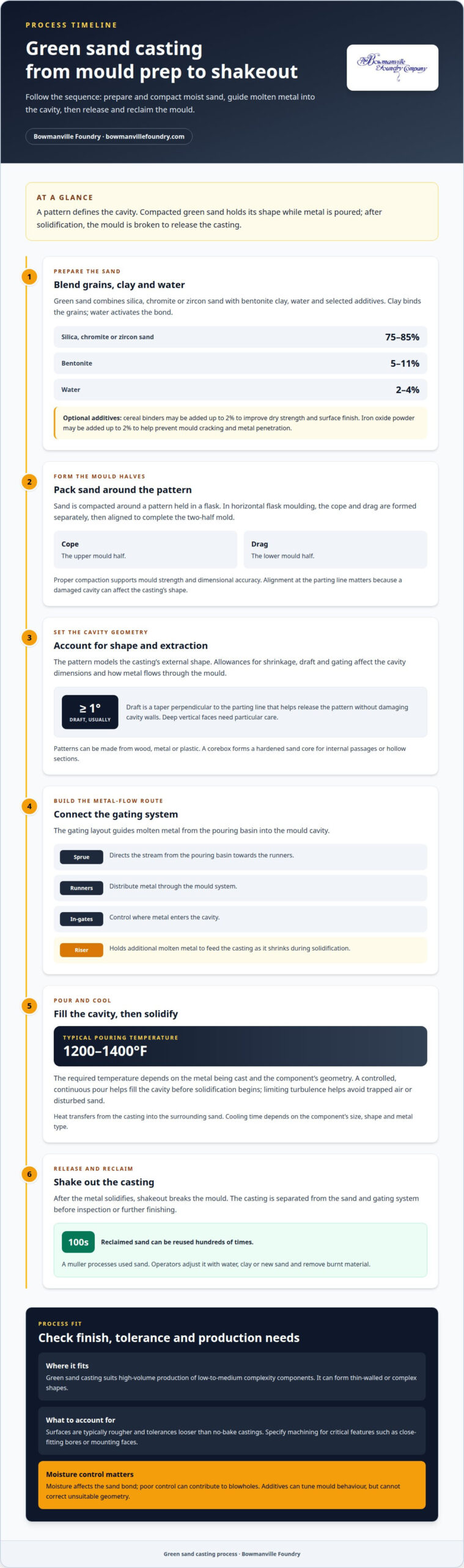
Green sand combines silica, bentonite clay, water and selected additives. Clay binds the grains, while water activates the bond. Common mixtures contain 75 to 85% silica, chromite or zircon sand, 5 to 11% bentonite and 2 to 4% water. These proportions influence mould strength and surface finish. Pre-cured sand cores form internal cavities.
Mould Preparation and Reuse
Sand is packed around a pattern held in a flask to form the cavity. Once the casting solidifies, shakeout breaks the mould and releases the part. A muller processes the used sand, and operators adjust it with water, clay or new sand while removing burnt material. Reclaimed sand can be reused hundreds of times. A pattern, flask and muller support these steps.
Cope-and-Drag Compaction
Horizontal flask moulding forms the cope and drag separately by compacting sand against the pattern. The cope is placed over the drag to complete the two‑half mold. Proper compaction supports mould strength and dimensional accuracy. Alignment at the parting line is also important, since a damaged cavity can affect the casting’s shape.
Temperature and Moisture Levels
Green sand commonly contains 2 to 4% water, and metal is typically poured at 1200-1400 degrees Fahrenheit. Moisture binds the sand, but poor control can contribute to blowholes. Compared with investment casting, green sand is less precise but more economical; compared with die casting, it is more flexible but less accurate. Additives and sand condition help manage mould performance.
Patterns, Runners, Sprues and Risers
Pattern geometry defines the mould cavity, while the gating system guides metal into it. Both affect casting dimensions and fill.
Pattern Design and Allowances
A pattern models the casting’s external shape and includes allowances for shrinkage, draft and gating. These features affect cavity dimensions and whether the finished part meets dimensional requirements. Pattern design also determines where metal enters and how it flows into different mould sections.
Pattern Extraction and Draft
Draft is a taper perpendicular to the parting line that helps release the pattern without damaging cavity walls. The taper used for extraction is usually at least 1 degree. Deep vertical faces need careful attention: insufficient draft can tear compacted sand and reduce mould strength, affecting the shape transferred to the casting.
Pattern and Corebox Making
Patterns can be made from wood, metal or plastic. Manual tooling can also use wood or plastic. A corebox forms the hardened sand core that creates internal passages or hollow sections. Pattern and corebox geometry must match the part design, because errors can carry through to the cavity and finished casting.
Runners, Sprues and Risers
Molten metal flows from the pouring basin through the sprue, along runners and through in-gates into the cavity. The sprue directs the stream; runners distribute it, while in-gates control entry. A riser holds additional molten metal to feed the casting as it shrinks during solidification. For iron component designs, explore Ductile Iron Castings.
Pouring and Solidification
Pouring moves molten metal through the gating system and into the prepared cavity. Metal flow and cooling affect how fully the component forms.
Molten Metal Pouring
The foundry pours molten metal from a ladle into the mould’s pouring basin. From there, the metal enters the sprue, which directs it toward the runners and in-gates. Green sand casting metal is typically poured at 1200-1400 degrees Fahrenheit. The required temperature depends on the metal being cast and the component’s geometry.
A controlled, continuous pour helps fill the cavity before the metal begins to solidify. The pouring rate and stream must also limit turbulence, which can trap air or disturb the sand. These factors matter because inclusions and incomplete filling can affect the casting’s integrity and finish.
Gating and Solidification
Runners distribute metal from the sprue, while in-gates direct it into the cavity. The gating layout determines how metal reaches different sections, including thinner areas that may cool sooner. A riser supplies additional molten metal as the casting shrinks during solidification, helping reduce shrinkage defects.
After filling, heat moves from the casting into the surrounding sand, and the metal cools into the mould’s shape. Cooling time depends on the component’s size, shape and metal type. Once the metal has solidified, shakeout breaks the mould. The casting is then separated from the sand and gating system before inspection or further finishing.
Green Sand Casting Applications and Limitations
Green sand casting suits high-volume production of low-to-medium complexity components. It can form thin-walled or complex shapes, but geometry alone does not determine suitability. Consider the required surface finish, dimensional accuracy and machining. Components with close-fitting interfaces may need machining on critical bores or mounting faces.
Green sand castings typically have rougher surfaces and looser tolerances than no-bake castings. Dimensional accuracy is limited, so specify machining when a critical feature must meet a tighter drawing tolerance. The moulding process establishes the initial shape, not the final precision of every interface.
Additives tune mould behaviour but can’t correct unsuitable geometry. Cereal binders may be added up to 2% to improve dry strength and surface finish. Iron oxide powder may be added up to 2% to help prevent mould cracking and metal penetration. Selection depends on the sand system and casting requirements.
Green sand moulds can deteriorate and lose dimensional stability during extended storage, so production schedules must coordinate mould preparation with pouring. Manual and automated systems can both produce these moulds, but the choice affects throughput and sand-control needs. Choose green sand when reusable sand and production volume suit the part, and its finish and tolerance requirements allow the as-cast condition or planned machining.
Gray Iron, Malleable Iron and Ductile Iron Castings
Choose an iron grade based on the component’s service demands, geometry and required material properties, not the casting method alone. Consider part size, loading and the balance of strength and ductility needed in operation.
Bowmanville Foundry produces three grades of Gray Iron. Start with the drawing and specified material requirements, then match them to the appropriate grade. Don’t assume one grade suits every housing, bracket or other component. The part’s function and operating loads should guide the decision.
Malleable Iron is used for small castings requiring good tensile strength and ductility. It may suit compact components where those properties are central to performance. Assess the part’s dimensions and specified loading alongside its required material properties.
Ductile Iron combines high tensile strength with good ductility and is suitable for medium to large castings. This balance is relevant when a larger component must withstand stress while retaining ductile behaviour. The design and specified material requirements remain central to selection.
For a practical comparison, align the drawing, service conditions and required properties before choosing a grade. Discuss iron casting requirements with Bowmanville Foundry to help assess which material fits your component.
Bowmanville Foundry: Post-Processing Services and Technical Support
Bowmanville Foundry supports manufacturers assessing iron castings and post-casting work. Its post-processing services address finishing needs alongside the casting specification, keeping the finished component’s requirements in view.
Material selection is a useful starting point for a technical discussion. Bowmanville Foundry produces Malleable Iron Castings and Ductile Iron Castings. Malleable Iron suits small castings needing tensile strength and ductility, while Ductile Iron combines high tensile strength with good ductility and suits medium to large castings. Component size, service demands and drawing requirements help shape the choice.
For early-stage planning, the Free Casting Buyer’s Guide provides information to support casting decisions. It helps procurement teams and design engineers consider material selection and part requirements before moving a project forward. CAD files and drawings can also provide a clear reference for a technical discussion.
An on-site technical/sales engineer visit is another option when a component’s geometry, material requirements or production needs call for direct assessment. Reviewing the part at your facility can help clarify design considerations and the path from casting requirements to a finished component.
When discussing a project, share the component’s intended use, drawings and material requirements. These details give the technical conversation a practical basis, whether you are assessing an existing design or planning a new casting.
Contact Bowmanville Foundry to discuss your casting requirements.
Move from Process Knowledge to Part Requirements
With the green sand casting process explained, the next step is to relate process choices to the component’s service demands. Consider the drawing, required material properties, critical dimensions and finishing needs together. This gives your casting discussion a clear engineering basis instead of treating the moulding method as an isolated decision.
For a project in development, bring the part geometry and intended operating conditions into the conversation. For an existing component, identify the features that must meet drawing requirements and any finishing operations needed after casting. These details help focus a technical discussion on design suitability and material selection.
Bowmanville Foundry provides iron casting expertise and related support for manufacturers assessing project requirements. A direct conversation can clarify the information needed to move from an initial specification toward a practical casting plan.
Contact Bowmanville Foundry to discuss your component and next steps. A well-defined set of requirements is a sound place to begin.
Frequently Asked Questions
What is Moulding Sand?
Moulding sand is prepared material used to make casting moulds. Its performance depends on how it compacts, holds its shape and allows gases to escape during pouring. For a design with a narrow passage or detailed surface, these properties affect how reliably the mould reproduces the feature. Foundries control the sand system to suit the part and production method.
What is green sand casting and how does it work?
Green sand casting uses uncured moulding sand that retains natural moisture when metal is poured. “Green” describes the sand’s condition, not its colour. The mould is not made rigid by baking or chemical curing. Its ability to hold its shape depends on the prepared sand and compaction, which must suit the component’s geometry.
What materials make up green sand for casting?
Green sand uses silica sand, bentonite clay and water, with additives selected for particular moulding needs. Some foundries use coal dust, wood flour or silica flour to improve surface finish or help reduce defects. Additive choice depends on the alloy and sand system. These ingredients modify mould behaviour, but do not replace control of the mixture’s condition.
What are the steps in the green sand casting process?
Sand testing and adjustment help keep the moulding system consistent between production cycles. A foundry can use a methylene blue test to indicate clay levels. After shakeout, a muller processes reclaimed sand, and operators can adjust compactability by adding water, clay or raw sand. These controls prepare the mixture for subsequent moulds.
What metals can be cast using green sand moulds?
Green sand moulds can be used for cast iron, aluminium alloys, brass and bronze. The alloy determines the component’s material properties, while its pouring behaviour affects moulding requirements. The sand system must suit the metal’s thermal conditions and the part’s geometry. Choose the metal based on the component’s intended function, not the moulding method alone.
What are the advantages and disadvantages of green sand casting?
One production advantage is that reclaimed sand can return to the moulding system after shakeout, with adjustments to maintain its condition. Manual moulding may suit work that needs flexibility, while automated systems support higher production volumes but depend on precise sand control. Moulds also aren’t suited to extended storage, so their preparation must align with the planned production schedule.
